Here is a shot that reveals some unfinished business and some mediocre lighting. In a manner of speaking, this is a double tunnel. The first part of the post discusses the reasoning behind this peculiarity followed by a basic description of the construction of our cast tunnel portals which we featured in previous posts. We will conclude with some CPR drawings of one of the portals which hopefully you can download if desired.

The West Portal of the Tunnel with the three sections placed but not secured. Some additional rock castings, gravel and greenery will be added to finish the scene. The left edge of the
 portal fits into a slot cut into the rock casting, the cut having been made before the rock casting was installed. Behind the portal, a cast plaster tunnel liner can be seen covered with the handyman's secret weapon - Duct-tape. The liner is made in sections of two parts, each from a mold marketed by Woodland Scenics. This facilitates removal of the rock tunnel linings for track maintenance.
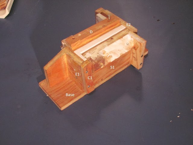
- Base
- E1& E2 = Ends
- S1 & S2 = Sides
- C1 = End Cap
- D = Dam
- T L = Interior Portal Lining
 The Form stripped.
Note that S2 is in place simply as a holder for the Dam D, fitted to the centreline. The left side will be poured separately.
The faces of all parts of the form have been clad in scale lumber. Mostly 3 x 12's. For the arch itself, 3 x 6's. Board lengths are 5 feet and 15 feet with joints staggered on 5 foot centres. Total length is 45 feet from the portal face. The form boards of the portal face (E1) align with the boards of the tunnel portal lining (T L). All corners have a 2" chamfer which I make simply by filing the edges at a 45 degree bevel.
Before pouring in the plaster, all faces of the forms are liberally coated with a release agent - in this case Pam cooking oil from a spray can.
There is a very interesting photo of a prototype concrete form for a Kettle Valley Tunnel in Barry Sanford's Book, McCULLOUGH'S WONDER: edition of 2002. It is found facing page 160.
Here is the CPR plan for the West Portal of Tunnel No. 1, Mileage 19.7. It is in two parts for scanning convenience. Its dimensions correspond closely with my field measurements. Interestingly, such is not the case when comparing field notes and drawings for the East portal of Tunnel 2.


Close examination reveals that the centre line of the portal is offset from the centre line of the track towards the inside of the curve. This offset increases as does the width of the portal, in proportion to the increasing sharpness of the curve. This is something to bear in mind as we plan our tunnels on curves. Not a bad idea to test for clearance with our 80 foot passenger cars or Big Boys with the very wide overhangs. In the case of our double Tunnel, the curves are prototypical; thus, we were able to build the portals to scale.
I hope this is of interest and assistance in your model building. I intend to publish more drawings in the future. In fact some of the posts may be heavy on the drawings and photos but light on text in an effort to shorten the time involved in creating a post. We will continue now with posting once a week on Wednesdays. As to future posts, readers' response and requests are solicited. Incidentally, I like my coffee black.
Coquihalla Man
Very nice, Anthony
ReplyDelete