There were three different "roundhouses" erected in Brookmere over the years. We will describe them a little with a view to helping model railroaders construct miniatures of these gems. The first of these was a three stall rectangular structure that of course was not really a roundhouse. Actually, the CPR term in all cases was "enginehouse" but we will use the terms interchangeably here in our posts. This first one was built fairly soon after the KVR established itself there in 1916 according to Joe Smuin's Kettle Valley Railway Mileboards. Here is a close up of the enginehouse from a photo published previously in the post for December 12, 2014.
From the same post, here is a close up of the station ground plan. Note that there are engine tracks either side of the enginehouse itself. These changed somewhat over the years according to local needs. Sometime in diesel days, they were removed. There is a cinder pit thirty feet long on the north engine lead and a depressed track for loading the cinders into gondolas. The bunkhouse to the east was an old car body assigned to house the watchmen and wipers. Somewhat less than a one star hotel. The engineman's bunkhouse was hardly better though it had a water supply and a telephone. At least they had a privy unlike the watchmen on the lower end of the scale. There are some dimensions given on the plan and the turntable is 70 feet long. From these the size of the enginehouse could be reasonably estimated. Note the telephone wires that run to the building from a junction near the Station. At some point, an office for the locomotive foremen was fitted into the rear of the station. Later on the foreman's office was moved to the new bunkhouse which was built in 1945.
Here is another shot provided by the Okanagan Archive Trust Society also published previously in the same post. This shows the side of the enginehouse with the tall windows and tall smoke stacks.
There are several photos in KV books which show the front of the enginehouse, notably Robert Turner's Steam on the Kettle, p. 60 (uppermost photo), and p. 58. The photo caption erroneously identifies this enginehouse as the one destroyed in the explosion in 1949. Another photo is to be found in Hal Riegger's The Kettle Valley and it's Railways, p. 215. The front of the enginehouse seems to be identical to the one at Hope which is shown below in another shot from the Okanagan Archive Trust Society. The locomotives appear to be of the D-9 class which were 4-6-0's, numbered 560 to 597 and were often used in passenger service in the 1920's.
The original Brookmere enginehouse was dismantled and a four stall house was built in 1944. The date on the drawings is 1936/7 but because of complications arising from the joint track arrangement with the GNR, construction was not undertaken until 1944 according to Joe Smuin's very reliable sources. One of these sources supplied a very helpful photo of the enginehouse and attests to its date of birth. The first recognition feature of this second Enginehouse is the placement of the window in the side wall close to the front doors. Otherwise, this house does not look much different than the one that replaced it in 1949. Compare this photo with with the similar image in the following post on BROOKMERE ROUNDHOUSE III.
The building was 90 feet long and each of the four rear walls was 27 feet wide. The front walls were 26 feet high and the rear walls were 19 feet high. In the upper part of the first drawing are seen the posts and girders that were erected between the stalls. Note the size and spacing of the "purlins" (roof joists). The size increases as the span increases from front to rear while the spacing decreases. To the purlins were affixed a roof of 2" x 3" 's on edge. These members were nailed hard to each other so that the roof was solid wood, 3" thick. It should be noted that solid wood is actually an effective fire resistant component; i e, it takes fire a long time to burn through. This was a common practice in construction of the time. Even up to the 1960's, fire walls in wood-frame apartment buildings were constructed in the same manner, but usually of 2" x 4" 's and sometimes 2" x 6" 's. The roof membrane is specified as Tar and Gravel although we cannot confirm its actual use. In the lower part of this first page, the faint outline of the original enginehouse from 1916 can be discerned.
Page 2 is the plan view. The building's walls were constructed of 3" x 8" plates and studs on 24" centres. There were two engine pits that were concrete-lined. Otherwise the floor was made of cinders. Only the tops of the piers for the posts would show. Purlins are set at right angles to the centre lines of the tracks on top of the main Girders which were 12" x 16". Many of the construction details will be made clearer in the next post with photos of the third enginehouse.
This third sheet shows the outside wall (called "end wall" on the drawing) with internal framing that is similar to the posts and bracing shown in the first sheet. Many windows are provided for as there was no electric light available. Wall sections and details are also provided. The wall studs would be exposed as there would be no internal wall finish. No insulation other than two layers of building paper between the ship-lap and the 6" drop siding (a k a novelty siding). Heating would be provided by whatever locomotives had a fire going. Oh, how we don't miss the good old days! Can you imagine working on the iron horses with large steel wrenches and other heat-drawing tools in your hands in sub zero weather - even with gloves on? Here is a drawing of a smoke jack that predated the one shown in page 1. It differs principally in not having tapered sides but this drawing is included here to help with dimensions and to illustrate the methods of construction and installation. This item would be built up of solid 2" x 2" lumber in the various sections shown on the right side of the drawing.
Our final drawing is from another source and shows all the detail for "standard" enginehouse doors. It is dated 1945 and would probably be correct for this enginehouse. Placement of the "wicket door" (man-door) might vary with the local situation. The glazed door was not an option to be found on the Brookmere roundhouse.
This is the roundhouse that was destroyed in the boiler explosion in March, 1949. A distant shot of it can be seen in Turner's book on page 60, the middle photo. There is a photo of the damaged roundhouse in Joe Smuin's other book, Canadian Pacific's Kettle Valley Railway, published by BRMNA, p. 28. On page 29 is seen the third enginehouse.
Next week we will continue with a drawing and photos of the third roundhouse for Brookmere. It is similar in many of the details to the one presented here although slightly longer at 100 feet. And perhaps our model will be ready for presentation. We have been busy with building it and then a trip to the Bayrails Operations meet in San Francisco. So, we have been a little short on time for the blog.
A working locomotive turntable is always interesting and appealing. We are happy to say that ours is finally in working order after years of manual semi-operation. It was built so long ago that some of the details of its construction may be lost in the mists of time, but the main points will be addressed here. The particular method of construction is a little out of the ordinary, a wood lathe being the major tool used to achieve accuracy. Care was taken to align the pit hole, the seat for the centre bearing and the turntable shaft.
Pit Construction: The model pit was built of 6 segments of white oak, glued up
with splines or woodworking "biscuits" between the segments. It was turned on a wood lathe and a clearance hole bored for the shaft. A seat for the ball bearing was cut into the underside of the pit. The wood has remained very stable for about 30
years. In the photo you can see the joints of the segments near the centre hole. In shaping the pit, we worked off dimensions which we had taken in the field at the site of the former Brookmere railyard. The owners of the property at the time were nicely accommodating and made the roundhouse area accessible. Note the coping timbers under the rails on the perimeter of the pit. These are detailed in the prototype drawing presented in the previous post.
Pit Rail and Wiring: During the turning process, a recess for the pit rail was cut into the appropriate place which made fitting the rail in place quite straightforward. After installing the completed pit into the layout, gaps were cut in the pit rail for isolating the two halves of the rail due to their opposing polarity. This is called a split ring pick-up and is sufficient for d.c. systems. With DCC it was found necessary to cut a second pair of gaps to completely isolate the bridge pick-ups for a second or two during rotation. DCC rails are always hot. The minor drawback with the split ring system is that sound and light
are turned off for a second as the bridge is momentarily isolated on the
dead section of the pit rail. We can live with that. A more complicated system of wiring the bridge is to use the pit ring for one wire and a centre shaft take off for the other. This method works fine with d.c.train control systems but for DCC it is necessary to wire in a reversing circuit breaker.
Bridge Base: Here is the underside of the bridge showing the wood base, electrical pick ups, shaft and mounting plate. The wood base for the bridge was also turned on the lathe as a disc and a 3/8" hole bored through and true. When demounted from the lathe's face plate, it was sawn to width with the 3/8" shaft hole kept on centre. A piece of aluminum plate (1/8") was prepared for the base, a centre hole bored and screw holes bored for mounting to the wood base. During mounting, the centre holes in the mounting plate and the one in the wood base were carefully aligned to keep the assembly centred. The brass shim (.002") under the aluminum mounting plate was necessary for final truing up of the table to the pit and engine leads.
Turntable Shaft: As mentioned, a recess for a ball bearing had been cut into the dead centre of the pit on the underside while being turned. The bearing was trued up and glued in place with Urethane Glue. The bearing takes a 3/8" shaft made of cold rolled steel. The shaft does
not actually touch the hole seen in the pit photo, passing clear through to the
bearing located in the bottom of the pit. The top end of the shaft had a shoulder cut into it for fitting hard to the aluminum mounting plate. This was done on a metal lathe by my friend Mike, a MMR. He also drilled and tapped the top end for a machine screw and fabricated a solid washer. A "flat" was filed on the bottom of the shaft to take a set screw. This set screw is part of the coupling for the drive system that we will reference below.
Bridge Wiring: In the photo above, can be seen the brass stock glued to the wood base. Pick-up shoes (by Tomar) are soldered to this brass stock and two wires run to the appropriate Bridge rails.
Bridge Deck: The ties and timbers were applied to the wood base according to the specifications in the prototype plans (see previous post). The walkway planks have a removable middle section for access to the machine screw and washer for future maintenance purposes. Rails were laid and wires soldered to them. Care was taken to install the rails in exact position relative to the centre point of the shaft and the centre line of the table. Each of the approach tracks were then laid so that both ends of the table track were able to line up with it. Some minor adjustment was required with each approach track and as well as the bridge rails till every rail lined up every time.
Bridge Girders are
resin castings from masters made by friend, Brian Pate of Klondike Mines Railway
fame. http://www3.telus.net/KMR/ He has two of the 70 footers on the CPR portion of his layout at Sicamous and Arrowhead. Thank you Brian. Nicely done and much appreciated.
One detail still to be modeled is the hoses that were connected to the piping to supply air to the motor from a locomotive. This is seen in the Lawrence photo from1954. There are a few other minor additional details that could yet be added to the bridge and pit.
Model Bridge Motor: From the prototype photos and the one appearing in the Hal Riegger book,
the various dimensions for the model were calculated starting with the wheel and sprockets. The
toothed sprocket was reckoned to be 33" in diameter as was the sprocket
paired up with the drive wheel. Two wheels from the Walthers'
Old Time Coal Conveyor were used for the sprockets, cutting out half of the
spokes: (Walthers Part # 933-3520). Glued to a Tichy plastic 33" wheelset as the drive wheel, it was a good match to the prototype. Judge for yourself. The model drive wheel is suspended above the pit rail so that it does not touch it. The brass rods simulating the prototype braces were enough to hold the motor rigidly. When in motion, the external sprocket does not rotate as the prototype did but if one of the readers figures out a way to do it we would be most interested to hear about it.
Turntable Drive: Initially, this model was a "finger-strong" turntable. Now it has a
wonderful drive system made by New York Railway Supply: http://www.nyrs.com/
It works perfectly but for quite a while it did not. This was due
to a technical inexactitude by, yours truly, the builder and blogger. Now corrected, the turntable does
what it is supposed to do.
Control panel: Using components from New York Railway Supply, a custom panel was fabricated. The pointer of the rotary switch simply indicates which of the 7 tracks the crew wants the Turntable to line up with. It does not power the track. The toggle switch indicates which end of the Bridge will line up with the chosen track. The 5 engine storage tracks have gaps cut in one of the rails to allow
the engines to be isolated from the electrical power when not in use.
Pressing one of the momentary-on push buttons will power the appropriate
track, thereby passing current to the locomotive to enable it to exit
the house under command of the engineman.
One interesting note: Happily, our model Bridge lines up with both the engine house track #2 and the main engine lead regardless of which track the head is oriented to. A long time CPR shop man told us that the actual Brookmere Bridge would only line up with both tracks in one orientation! Rotating it 180 degrees would result in the bridge rails lining up at one end only. So, if your bridge has this problem there is a precedent for it.
Some days we just have to watch the engines taking a spin on the turntable. Great stuff.
Having received a few questions and comments about our latest project, the Turntable and Roundhouse in Brookmere, we will give a detailed response here and publish plans and photos of the prototype and some details on our miniature interpretation of same.
In operating a model railroad, it becomes quickly evident why the prototype built these items because a method of turning steam locomotives is a vital necessity. The two most common methods for turning engines were the Turntable and the Wye. Sometimes a loop track was built and employed, an example of the latter being the loop at Princeton but these took up a lot of real estate so were rarely the preferred option. Incidentally, larger KV locomotives were restricted in their use of the loop track in Princeton which was a very tight 15 degrees of curvature.
It is evident that the 70 FT HALF DECK TURNTABLE was a fairly standard type for the CPR. The seventy footer was to be found at several locations along the southern mainline according to photographic evidence and documents in our collection. At least one is still in existence today in Victoria BC. On the southern mainline there were possibly ten located between Medicine Hat and Odlum. On the Kettle Valley Division, 70 foot Turntables were located at Brookmere, Allenby and Copper Mountain. This size was adequate for most steamers at the time of installation in the early part of the 20th century. But the P-1n class locomotives with the larger tenders coming on stream in the late 40's, were too long to be turned on them. This became a moot point as the larger engines generally were run between the major terminals which were equipped with larger tables. Shortly afterward, dieselization took place and the need for this device diminished.
The focus of our study today is the 70 foot turntable at Brookmere which served the railway well from 1915 until the passing of the steam locomotives. Here is a shot by my friend, the late Glenn Lawrence taken in 1954, shortly after dieselization. [Update: This is a clearer picture that has come my way from a mutual friend of Glenn's]
A few details to note here. The exterior engine storage track to the north of the engine-house has been removed but only recently. This track shows on the drawing from 1953 and in a photo from 1952. This is the only shot we have showing the drive motor from this, the exterior side. More about this later. The overhead piping to supply the air for the drive motor is cut off by the photo edge. The piping ran over to the pump house. Before the erection of the pump house at the time of the Bunker "C" Oil facilities, the table was powered by means of the engine air supply which was fed through the hoses seen on the deck in the foreground. Hoses were also fitted at the other end, hence the pipe that runs the length of the turntable. Part of this pipe was removed sometime later as it does not appear in the Lawrence photo published in a previous post and herewith presented again.
The pole to the right (or east) of the pit in both photos has a cable running to another pole on the opposite side of the pit. This cable supports the air line which, as we said, was run to the pump house. I suspect it ran down the post and went underground from there. The drive motor appears in a photo from 1944 but of its existence earlier than that we cannot say.
Here is a Lawrence photo taken on the 1968 trip. Extraneous marks appear in the original. Unfortunately, there do not appear to be measurements or drawings of it. Hal Riegger published a good photo of it on page 216 of his book, The Kettle Valley and its Railways. The Victoria turntable drive motor is quite different.
This photo is a recent acquisition and was taken by a fellow KVR modeler when it was lying discarded in the pit many years ago. Apparently it has disappeared since. At some point - probably 1970 or so - the bridge was cut up for scrap, leaving the pedestal and the centre core of the bridge which still sits there to this day (on private property). As can be seen, there is a great deal of gear reduction designed into the drive mechanism. The interior sprocket is paired up with the drive wheel the flange of which is seen projecting slightly past the teeth. The bracket seen on the left was bolted to the girder side of the Turntable.
Another shot which may be of interest to the modeler, is this one of a section of the turntable pit taken in the 1980's.
The gap in the upper concrete rim is the opening for the "coping timbers" on which the rails were placed. They functioned as cross ties in stead of the rails sitting directly on the concrete. The rails in this location were the turntable leads on the west end of the pit. It would seem that the pit rail was shimmed with the many wood wedges pictured to get it true to the table and the drive wheel. The vertical lines on the inner wall are rust stains caused by rain water running off the gullies in the horizontal part of the pit wall.
Here is another shot by Glenn Lawrence showing detail of the bridge deck which is useful for modeling purposes. The exposure has been lightened up to better provide detail. Note the pole to the right (or west) in the photo which supports the air pipe previously mentioned.
Another photo of interest is one to be found in J. F. Garden's book, The Crow and the Kettle. On page 37 is shot of a C-Liner posed on the turntable at Crowsnest. The rails of the table are higher than those of the leads and this was standard practice. Refer to the drawing below which specifies a 1" difference. The need for this was seen in a movie of a CNR locomotive edging on to a turntable with the result that the table very definitely sagged under the weight of the locomotive as the Drivers contacted the bridge rails. This would not be a design feature for model builders to adopt.
Finally, we present a CPR drawing of the turntable and pit with all the detail necessary to build one in scale or full size even!
The drawing was made by a gentleman, initials "MG" who published various other drawings in the 1985. I bought a set when first released and have not heard of him since. Efforts to trace him or his company, Mainline Design Group, have been fruitless. I truly hope that he is agreeable to my publishing this rendition of his drawing. This is a not-for-profit Blog site and our motivation is to further the hobby and help modelers with accurate information for their building purposes. I have no interest in collecting stuff, just to "have it". Or in making money off a hobby. The original was drawn up 100 years ago and I doubt that a copy of an original falls within copyright laws since it is in fact, a copy - albeit, a beautifully rendered one.
For some additional photos of another CPR 70 foot turntable check out the one that was located in Goderich Ontario: http://www.trainweb.org/oldtimetrains/CPR_London/goderich_turntable.htm
Next post will be a description of how we built a model of the Brookmere Turntable.

 There are some dimensions given on the plan and the turntable is 70 feet long. From these the size of the enginehouse could be reasonably estimated. Note the telephone wires that run to the building from a junction near the Station. At some point, an office for the locomotive foremen was fitted into the rear of the station. Later on the foreman's office was moved to the new bunkhouse which was built in 1945.
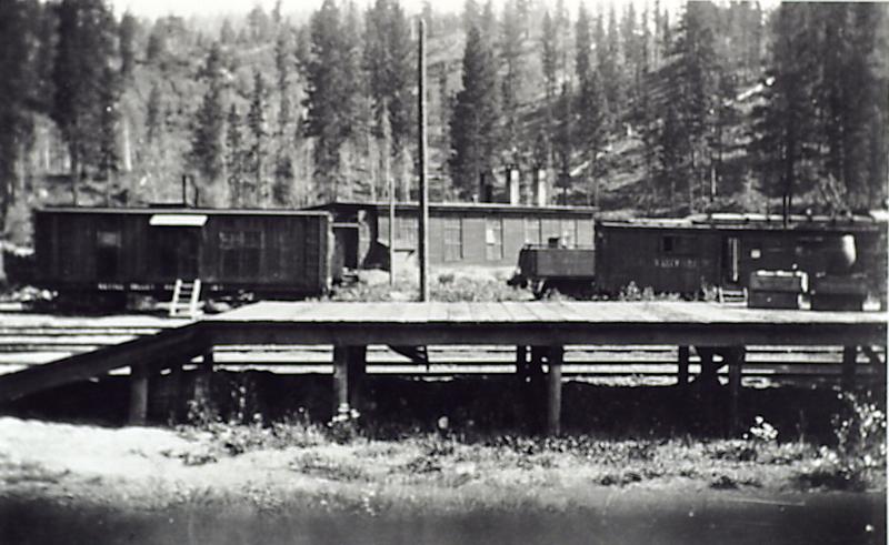


 Here is a drawing of a smoke jack that predated the one shown in page 1. It differs principally in not having tapered sides but this drawing is included here to help with dimensions and to illustrate the methods of construction and installation. This item would be built up of solid 2" x 2" lumber in the various sections shown on the right side of the drawing.


.JPG)


