Wednesday 26 February 2014

THE STATION AT MIDWAY, BC


Midway was mile "0" for the Kettle Valley Railway and its successor, the Kettle Valley Division of the CPR.  This photo shows the well-preserved station building shortly after it had ceased to function as the local railway agency.  It is appropriate that the station serves today as the local museum because the railway played a significant role in the life and history of the town and the surrounding area.  This is a CPR Standard No. 5 Station which was very common in small towns throughout the west.  Prairie versions often had a significantly extended freight section next to the baggage room.  Individual stations varied in some of their details.

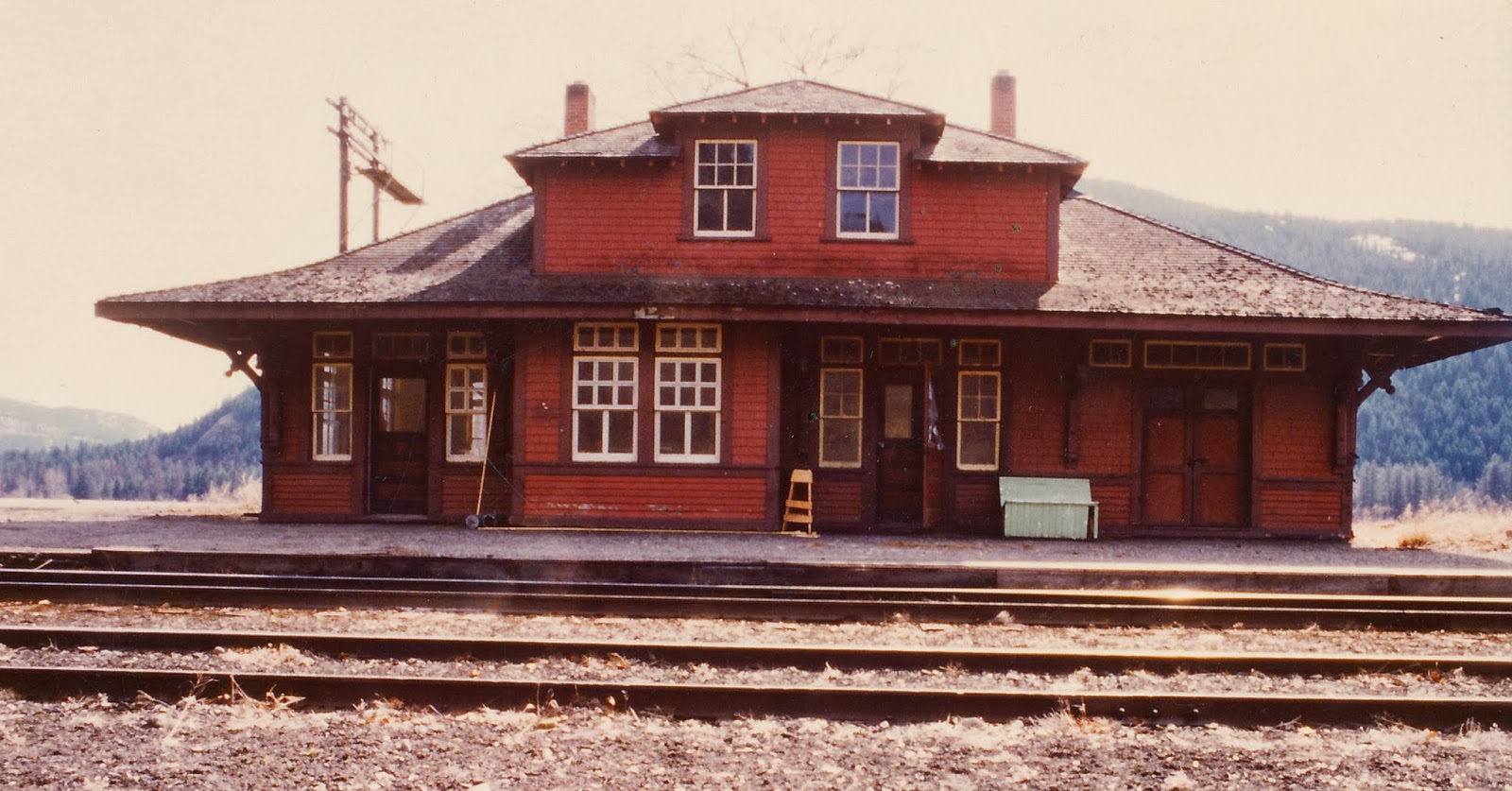
In today's post, we will provide some information and drawings for this handsome structure that the CPR erected in Midway about 1909 according to Joe Smuin's Kettle Valley Railway Mileboards.  The plans presented here were hand-drawn by Coquihalla Man in late 1984 from field measurements taken that summer.  The family were nice enough to indulge my request to accurately record the details when we stopped for a few hours on our way to a vacation in the West Kootenays.  We stopped on our way back as well for a few more.

Here is the Front Elevation with 2 critical dimensions for scaling your print.
Here is the East Elevation.  In this view, the East Annex is visible.  My guess is that this addition was made sometime later as the windows and trim are non-standard but the wall finish has been duplicated: drop siding, water table, sidewall shingles, corner boards.  Presumably, the station agent and his family were in need of more living space.  Another detail to note is the platform which in this view is a wooden one while the West end elevation shows a gravel version.  There is a published photo in Robert Turner's book (West of the Great Divide, p.270) showing a Dayliner at the Midway station with a planked platform in evidence, the details of which are shown here.  It has a slight fall or slope towards the track.  The height of the track relative to the platform is taken from CPR plans of other stations. 

Here is the West Elevation which shows another annex.  This time the wall finish is different than the main building and again the windows are non-standard, even differing from those of the East annex.  This suggests that this West annex is an even more recent addition than the other.  Note different positions of chimneys with respect to centre-line and front elevation as well as their different widths.   This elevation has details of the gravel platform that graced the front of the station in her latter days.  It would seem that a freight door was original to the station but at some point, it was boarded up - perhaps when the West annex was added on.
Here is the rear elevation.
In reproducing these drawings, measure between points on the building; e g, 50'-0" length, and try to get your computer print as close to 50 scale feet as possible.  Check for height as well.  Photocopiers will often distort heights one way and lengths the other.  The critical dimensions are:
  • length 50'-0"
  • width  21'-6" 
  • height 25'-0"
Downloading the plans and printing them in HO scale is not too hard.  I actually figured this out by myself.  Here is my method.  There may be other ways but this works for me on my H-P laptop.
  1. Copy plan image to a Word Document
  2. Click Page Layout tab
  3. Click Margins tab and select Narrow
  4. Click Orientation tab and Select Landscape
  5. Click View. Select Zoom This offers an enlarging or reducing percentage
  6. Take a sheet of 8 1/2" x 11" paper and hold it to computer screen, adjusting Zoom till length of Word Document matches 11" dimension of paper sheet.  In my case that is 105%.
  7. Click on image.  A border will appear.  Move cursor to lower right corner of border.  Click and hold on the tiny box, moving arrow diagonally down and to the right.  Release and allow image to stabilize.  This adjusts both dimensions of image.  You may have to move cursor off the page but that is okay.  The critical thing is to move the corners of the image on the diagonal.
  8. With a scale ruler measure the length of the building.  Move cursor and arrow diagonally outwards to enlarge.  Move cursor diagonally inwards to reduce.  Adjust till length of building matches 50' mark on scale rule.  The height should be in scale as well.
  9. Check height with scale rule.  Should be 25'.  If building image is too short or too high, you can adjust this to get it right without changing the length.   To adjust height only, place cursor on tiny box at bottom centre of border.  Click and hold, pulling the cursor down to stretch the image or up to shrink it.  By trial and error you can get this  dimension to be correct.  Everything should then be in scale and drawing can be measured for details.  This is amazing and so much more accurate than using a copier.
  10. Print and check dimensions.
The next post will present the floor plan and a photo of my model version with its complex though attractive roof line together with some modeling suggestions to produce this in scale.  Later posts will provide a station ground plan of Midway and a description of its facilities with modeling in mind.

See you next Wednesday.

Coquihalla Man


Wednesday 19 February 2014

A MEDIUM DOUBLE TUNNEL PLEASE


Here is a shot that reveals some unfinished business and some mediocre lighting.  In a manner of speaking, this is a double tunnel.  The first part of the post discusses the reasoning behind this peculiarity followed by a basic description of the construction of our cast tunnel portals which we featured in previous posts.  We will conclude with some CPR drawings of one of the portals which hopefully you can download if desired. 
For the transition between the scene in THE TUNNELS post and the next scene, I decided on this medium double tunnel by which I mean that the tunnel through this mountain outcrop is actually a composite of the prototype's tunnels 2 and 3.  The east portal (right) is that of Tunnel 2 and the west portal (left) is that of Tunnel 3.  They are 1/2 mile apart in reality but the west portal opens up onto another scene that was very appealing for reasons we will discuss in another post.  Tunnel 3 is 272 feet long and this model version is quite close.  For the Coquihalla Subdivision, this is one of the medium-sized tunnels which ranged in length from 164 feet (No. 7) to 556 feet (No. 10) according to Joe Smuin's Mileboards.  In all, there were 12 Tunnels on the Coquihalla Subdivision most of which received the concrete portals starting about 1940 as the timber-framed originals required upgrading or replacement.  

The West Portal of the Tunnel with the three sections placed but not secured.  Some additional rock castings, gravel and greenery will be added to finish the scene.  The left edge of the portal fits into a slot cut into the rock casting, the cut having been made before the rock casting was installed.  Behind the portal, a cast plaster tunnel liner can be seen covered with the handyman's secret weapon - Duct-tape.  The liner is made in sections of two parts, each from a mold marketed by Woodland Scenics.  This facilitates removal of the rock tunnel linings for track maintenance.

From field measurements, I drew up plans for the various portals and then built a wood form with which to cast them in Hydrocal plaster.  The form is portrayed in photos below. 

Key:
  • Base
  • E1& E2 = Ends
  • S1 & S2 = Sides
  • C1 = End Cap
  • D = Dam
  • T L = Interior Portal Lining
The Portal is cast in three steps resulting in three pieces.  A Left Half, a Right Half and the Lintel.  Here is the form with the right half poured and set.  This casting is the same as the right half of Portal No. 1 West and will be used for No. 3 West. From this one basic Interior Tunnel Portal Lining form (T L) and several different outside forms, many different portals can be cast. 

The Form stripped.

Note that S2 is in place simply as a holder for the Dam D, fitted to the centreline. The left side will be poured separately.  
The faces of all parts of the form have been clad in scale lumber.  Mostly 3 x 12's. For the arch itself, 3 x 6's.  Board lengths are 5 feet and 15 feet with joints staggered on 5 foot centres.  Total length is 45 feet from the portal face.  The form boards of the portal face (E1) align with the boards of the tunnel portal lining (T L).  All corners have a 2" chamfer which I make simply by filing the edges at a 45 degree bevel.

Before pouring in the plaster, all faces of the forms are liberally coated with a release agent - in this case Pam cooking oil from a spray can.


There is a very interesting photo of a prototype concrete form for a Kettle Valley Tunnel in Barry Sanford's Book, McCULLOUGH'S WONDER: edition of 2002.  It is found facing page 160.
 
Here is the CPR plan for the West Portal of Tunnel No. 1, Mileage 19.7.  It is in two parts for scanning convenience.  Its dimensions correspond closely with my field measurements.  Interestingly, such is not the case when comparing field notes and drawings for the East portal of Tunnel 2.


Close examination reveals that the centre line of the portal is offset from the centre line of the track towards the inside of the curve.  This offset increases as does the width of the portal, in proportion to the increasing sharpness of the curve.  This is something to bear in mind as we plan our tunnels on curves.  Not a bad idea to test for clearance with our 80 foot passenger cars or Big Boys with the very wide overhangs.  In the case of our double Tunnel, the curves are prototypical; thus, we were able to build the portals to scale.

I hope this is of interest and assistance in your model building.  I intend to publish more drawings in the future.  In fact some of the posts may be heavy on the drawings and photos but light on text in an effort to shorten the time involved in creating a post.  We will continue now with posting once a week on Wednesdays.  As to future posts, readers' response and requests are solicited.  Incidentally, I like my coffee black.

Coquihalla Man


Thursday 13 February 2014

TUNNEL PORTALS OF THE MODEL KIND

In the previous post I described the adventure of the field work to record the features of the Tunnel Section of my layout.  Today we will look a little closer at the tunnel portals.  In a future post I will describe a few details of their construction.

Mileage 19.7  The West Portal of prototype Tunnel No. 1 is a bit worse for wear but still intact if the CPR would like to reopen the line!  A few scratches but still serviceable? -  maybe not.  They would have to muck out a fair amount of rock and gravel as the interior has completely collapsed.  The rock shed part of the portal extends 45 feet into the mountain as noted on the plans which the  Engineering Department of CPRail graciously allowed me to acquire from their extensive plan room back in the 1990's (now closed).

Evidently, all the portals and rocksheds of the Coquihalla were originally constructed of Wood Timbers but the CPR upgraded them to concrete in the 40's and 50's.  Even so, the interiors of the tunnels were often lined with 12" x 12" timbers called Tunnel Sets.   According to Joe Smuin's Kettle Valley Railway Mileboards, the tunnel itself was 218 feet long when the west portal was built in 1947.  The east portal was rebuilt in concrete in 1951.

Here is the model, the "concrete" looking fairly fresh as it would be only 2 years old in 1949, my target year for the layout.  By the time that I acquired the official CPR drawings, I had already built the portals from field measurements out of Hydrocal plaster. This ideal modeling medium was poured into a wood form to create the replica in 1:87 scale.

From the plans, I learned that the prototype tunnel was constructed on a 200 foot spiral to an eight degree curve but I had guessed wrongly that the track alignment was still fully curving as it left the portal.  I am glad that I proceeded with this engineering "inexactitude" as it turned out, because I think the scene actually looks better with a curve as can be seen in a photo of the previous post.  Besides, as zealous as I am for prototype modeling, it is too much to rebuild for what is a minor discrepancy.

Mileage 19.9  Now a photo of the East Portal of Tunnel No. 2.  The Prototype:


Both portals of Tunnel 2 were built in 1943 and the total length was 280 feet.  There was a 10 degree curve right as the track entered the east portal ending in a 200 foot spiral as it left the west portal.  Interesting colour in the rock.


And the Model:

That foreground gravel and rock is the real deal, collected from the slopes of mile 19.  However, the caboose is not constructed out of wood and steel from a real one.  Looks like we need a little more colour and some greenery to liven things up.  Plans and field notes should appear in a future post as well as a few details on how they were built.

 
I invite your comments and questions.  Not sure what the procedure is.  If someone knows, clue me in because I am new at this.

Coquihalla Man

Monday 10 February 2014

THE TUNNELS

Engine 3629 is pushing hard on the tail end of an Eastbound freight in the upper Coquihalla Canyon having just exited Tunnel No. 2, mileage 19.9.  The road engine is probably another 3600.  The train is a little shorter than normal so there are only two engines working this freight.  It was common for three engines to work a freight on the Coquihalla Subdivision during steam days, two being on the head end.  Of course we know this is a model as there is no smoke in evidence - thick black stuff would be pouring out of their stacks.  Bill Sornsin, a visitor from Seattle, took this great shot in the thick of an operating session, with him at the throttle of the pusher.  He timed it perfectly.
On the labour day weekend of 1991 or so, my wife and I went to my happy hiking ground in the upper Coquihalla Valley to do some field research.  One thing that had grabbed my attention was a photo of the tunnels #1 and #2 published in Roger Burrow's Railway Mileposts, Vol.II.  This particular view, looking west, struck me as an ideal subject to model: sheer cliffs, spectacular tunnels, interesting portals and a short distance between them.  We measured the distance with the odometer in my truck and then measured all 4 portals, taking many pictures with a 35mm Minolta camera.  Remember those days of print film.

As it turned out, the entire scene including the two facing portals could be modeled in 12 feet at 1:87; i e full scale.  Wow!  This was getting interesting.  So,we hiked down the slope to the river, splashed across (not very deep) and up the other side to a vantage point somewhat higher than the right-of-way across from us.  It was tough going in the loose gravel and the bush but I was breathing just as hard from excitement as from exertion.  Taking photos in succession east to west, we caught the whole scene and then zoomed in for some detail shots.  We returned to the truck and started for home happy - very happy.  Here is one of the shots from across the valley showing the east portal of Tunnel No. 2.


I was thrilled with the pictures and went to a copy store to enlarge them on copy paper and stitched them together - remember when actually we cut and pasted with paper and glue stick.  Then I drew a grid on the sheets to aid in modeling for proportions and overall scale.  It was fairly easy to do.  A month or two later I was ready to build.  Company work was a bit slow, so I took a week off and devoted the time to building it.  About 60 hours passed very pleasantly.  At that time the tunnel portals were omitted and the track just disappeared into a holes at either end of the module.  But everything else was complete in the 12 foot section.  We installed it on the wall, anchoring it with screws through the solid framework into the wall studs.  We took it down 3 or 4 years later to build and install the tunnel portals and tunnel linings.  Reinstalled shortly after, it has hung there with no movement or sagging for years.  Adjacent sections were built in time for the NMRA convention in Seattle in 2004 when some convention attendees made the trip north for tours and operations sessions.


Much later I acquired CPR drawings for the right of way and also the portals themselves.  Both documents confirmed the site measurements and estimates but I was a little off in the track alignment itself.  Nevertheless, I was not in any way disappointed by that discrepancy preferring the model's S-curve with their complementary super-elevations that are nicely evident in the photo.  The story of how I acquired the drawings is a story for another day.

Happy Hiking;

Coquihalla Man