Thursday, 27 March 2014

MODELING CANADIAN PACIFIC TANK CARS


Extra 3628 East works upgrade on the Coquihalla Sub with a train of loaded tank cars full of Bunker C Fuel Oil.  It is September of 1949 and these tank cars are "OCS" (on company service) destined for the various fuel storage tanks on the Kettle Valley Division.  The CPR has recently converted most of its locomotives to oil from coal and constructed the requisite storage and service facilities at Brookmere, Penticton and Carmi.  In addition to the OCS tanks, oil and gas were supplied to the many communities along the line as evidenced by the many private tank cars to be seen in the consists of Kettle Valley trains.

Modeling these CPR tank cars was an interesting and rewarding experience for me as they are somewhat unique and essential to my era and operations.  I provide here some photos and drawings of two different cars that were the most numerous on the company's roster.  In both cases, I was fortunate to photograph and measure the prototypes.  But unfortunately, the photos were loaned to a friend and lost.  CP Tracks carried an article and photos in Issue 11-1.  You can click on any photo or drawing for enlargement and downloading.


The "long one":  From the 1950 MP-14.  50 cars listed in series No.'s 389000 - 389049.  Built in 1923 & Jan 1924.  Length: 43'-0", capacity 100,000 lbs..  Here is a shot of two showing both sides.  Ladder is found on left side only.  Construction:  Athearn tank; Frame spliced from two Tichy frame kits.  Dome is small Tichy with a collar made from styrene.  Wire handrail and brass Handrail Brackets by Precision Scale (part number 32110).  Blackcat decals plus some custom dry transfers.
 
These drawings were made on 8 1/2" x 11" paper so you can scale them.  Originally drawn to 1/4" : 1'-0".
 
Here are some shots that my friend, the late Glenn Lawrence, took around 1960.  The cars are likely being unloaded of their Diesel fuel for the Vancouver engine facilities.  Glenn was very generous with his photos and resources as well as a very good modeler whom I met at the Vancouver Club in the CNR station.
 
The Short One:  From the 1950 MP 14.  101 cars listed in Series 389501 - 389719 .  Built 1912.  Length over Strikers: 32' - 7 1/2".  Capacity 80,000 lbs.


Proto 2000 Car Kit.  Added K-brake system and small plastic dome from Precision Scale (part number 32108.1).  Collar of Styrene with embossed rivets using dull needle.  Fabricated safety vents from styrene rod softened with a heat gun (hair dryer) Several tries to get it right.  Vent Caps from kit?  A brass version is available from Owl Mountain Models at http://www.owlmtmodels.com/detail_parts/detail_parts.html#Vents   Precision Scale brass handrail stanchions (part number 32110). Radial rivets from Archer Decals (original kit longitudinal rivets filed and scraped off.)  Accurail trucks and Intermountain wheelsets.  Blackcat Decals.

Drawings from measurements taken in late 1980's.  Car was to be moved for scrapping.
 
These drawings were done on 8 1/2" x 11" paper and can be scaled.

A very good photo of the prototype can be seen in the CP Tracks issue 11-1 and also in Nicholas  Morant's Canadian Pacific by J. F. Garden, pages 84 & 87.

This post is a little late due to much activity on the layout: Eng 925 got a lot of attention and is working well!  Lots of scenery and a road bridge for the logging trucks.  It is hard to break away from modeling when you are on a roll.

Hope to see some CPR tank cars by others eventually.

Coquihalla Man

Update Jan 3 2018: Part numbers added for handrail brackets and small dome.


Wednesday, 19 March 2014

OPERATING AN HISTORICAL MODEL RAILWAY

One of the great features of the model railroad hobby is the experience of an operating session.  Here I would like to offer a few thoughts on my efforts as a historical type modeler and miniature re-enactor.  

Briefly put, the layout comes alive.  We do more than run a few trains.  The model locomotives are chosen and detailed with respect to the real ones as in the late 1940's as is the rolling stock.  Scenes are modeled with a view to creating a photograph that could pass as a shot taken in the same period or even duplicating one taken a long time ago.  When we complete the scene in a time warp sense and operate our trains with the support of a Dispatcher and Station Operators, interacting with each other over the length of the line, we are participating in a role-playing game that brings the events of the past close to us who are mad about trains.  These events are rather hum-drum if we think about it as there are no wars waged, nor lives lost, no earth-shaking cataclysms or car-chases and explosions.  On the contrary, it is just the everyday movements of trains from A to B as they did 60 or more years ago on a backwater railroad in a sparsely populated corner of a vast and mountainous country.

This aspect of modeling the prototype; i e, working it as the real railroaders did is quite fascinating.  The more you formally do the jobs of the railroaders, the more you realize that there are things you do not know and would like to find out.  On the other hand, there are things you do not even know that you do not know and so do not have questions to ask.  Sometimes, this is realized in conversation or listening in on an exchange between two persons who make an off hand comment and you do not know what they are referring to.  For example, there was an entry-level job at Brookmere called the watchman and a couple of old-timer KV enginemen were making reference to a particular watchman's unfortunate accident and afterwards I asked them; "What did the watchman watch?"  They could not believe someone could ask such a basic question and after a moment of astonishment, they both replied; "Well, the engines of course!" Why did they do that?" I asked, to which they replied with a only little less perplexity,  "To see that they don't explode or lose their fire."  "Oh" said I.  And so I found out something for which I did not previously have a question.

So, over time I had come up with questions to ask the railroaders at the annual August reunions in Brookmere which was always an interesting event.  Sadly, many of the men I talked with at these "Brookmere Campouts" are gone now and with them their tales of yore.  However,  I was able to glean enough information and hear some of their tales to enhance the operations of a Kettle Valley Model Railway.  As this blog continues, I plan on sharing something of the experience of our operating sessions which are based as much as we can on the real railway and its method of operation.


Here was an interesting meet during a session last September's Vanrail event.  There are three trains here at Hope and another locomotive waiting on the Wye to couple on to the Extra 5101 which is itself waiting in the siding for No. 79 to pick up his orders and clear.   Squeezed onto the backtrack is the Eastbound way-freight which is eager to return to his assignment. The action varies a great deal even though there is a timetable.  Photo by Brian Ferris.

Any operating scheme must have some sort of structure, schedule or sequence of trains and herein I post copies of the Coquihalla Subdivision pages from two Timetables: a model version for use during operating sessions on the layout in my basement and a prototype one on which it was based.  In constructing the model version, schedules of trains approximate the times in and out of Brookmere.  And of course, the model version is considerably shorter than the prototype.  Here is the model version composed on a Word Document.


And a reproduction of the prototype Timetable No 94, September 1949:

I hope this is of interest to readers and is an inspiration to modelers to get operating or at least to plan for eventual operations of their layout.  For further reading on operations visit the Website of the Operations Sig at:  http://www.opsig.org/  and check out future posts here for more on a Kettle Valley Model Railway.

Coquihalla Man

Thursday, 13 March 2014

MIDWAY YARD

We present here a series of photographs that Dave Love, a modeler-friend of mine, took 

during several trips to the Midway area sometime in later diesel days.  You can compare these photos with the reproductions of the Midway "Station Ground Plans" which are included in this post.  Here are a few shots of the Station itself. 


Early Winter?  Trees bare and some snow in the distance.


Summertime and the living is easy...Dry grass and the tree in full foliage.  Enginemen's Bunkhouse in the distance.


A view of the yard looking west.  Note the stacks of raw ties to the right (north) and 4 loaded gondolas ready for lifting.  Tie shipments were a major commodity for the KV for many years.  

Station in the distance behind the toolhouse, Enginemen's Bunkhouse to the left. I think this Bunk House is later than that shown on the drawings.


Looking East at the yard throat. 

Not shown here are shots of the other buildings and yard features which Dave took to aid in modeling this area which could be made available if there is interest.  He is working on a module in HO scale with several of the structures complete already.  


This plan is of the Midway Yard in 1953  at the time of conversion to Diesel Locomotives when fueling facilities were needed at strategic points along the line.  There is a glimpse of the actual facilities in Hal Riegger's book The Kettle Valley And Its Railways.  (Page 97).  Also, as mentioned in the last post, The Crow And The Kettle, pp. 251.  None of this appears in Dave's photos, their being removed sometime earlier.  Note the addition of a "Back Track" to the West of the station that does not appear in the 1945 drawing.  This drawing also has a profile that gives track spacing and a few other details.


You will have to cut and paste these two images together.  They overlap.  It is shown here in two parts as my scanner works only for 8 1/2' x 11".

Here are the drawings of the yard showing the yard in steam days.  The last date of revision is 1945 having been revised or added to many times since first drawn up in 1928.  This revision seems to show the new location of the oil fuel facilities.  This would be the Bunker C oil for the steam locomotives which include Service Tank and Stand Pipe, Sump,and Pump House.  Also note the cinder pit with its depressed track as the KV and Kootenay divisions were still maintaining coal fired steamers.  The wholesale conversion to Bunker C would take place in 1949 when Oil Service Facilities were built in Carmi, Penticton, and Brookmere. 

In both drawings, the 40,000 gallon water tank shows.  Although this is a Division Point and Terminal, there was no coaling plant here, the nearest being in Carmi to the West.  In a possible future post I will treat of the remining structures in Midway from a modeler's point of view and provide some additional photos if there is interest.  This post is a bit late due to my working on the layout and getting it ready for an impending Operating session.

Dave Love has graciously consented to my posting of these shots.  In his words: "I'm happy for the material to be distributed and add to the collective knowledge."  Very generous of him.  He is partly responsible for my getting involved in things CPR as he gave me copies of prototype plans many years ago when we were both members of the Vancouver Model Railway Club, based in the downtown Vancouver CNR station.  Thank you Dave.


Tuesday, 4 March 2014

MIDWAY IN 1:87


An Eastbound freight idles in the siding at the Midway station.  It is unlikely that the Nelson-bound train-crew has their Clearance because there are no extra flags displayed.  The consist of this freight would have mostly originated in Penticton, destined for the East.  With the fresh crew coming on duty, they would have tacked on their conductor's caboose and perhaps a few loads from the local sawmills.  For short freights out of Penticton, single diesel units were not unusual in the latter years of the railway as numerous photos in Kettle Valley books evince.  The centre-line of the Station building is Mile "0" for the Kettle Valley and Mile 126.6 of the Boundary Sub, this being the mileage from Nelson. 

http://www.cprboundarysub.ca/images/Layout_pictures/IMG_7795.sm.jpg


This is Scott Calvert's Midway Yard on his former layout which has been demolished but you can see what used to be at: http://www.cprboundarysub.ca/.  A new and larger version of the CPR's Boundary Subdivision is under construction in the basement of his new home.  Nice fascia and graphics and a well executed backdrop make for a nice scene which does justice to the prototype.  Rene' Gourley painted this backdrop and did much other good work on the old layout.  Scott is a very good modeler and promoter of the hobby.  His new layout has every potential to become a Great Model Railroad.

It still hurts a little to think that the real rails are gone forever.  There is some consolation in the right-of-way being preserved as part of the Trans-Canada Trail with many of the bridges and a few of the station buildings still in place.  Equally consoling is the experience of seeing and operating model versions of the now-truncated Southern Mainline.  Another fine layout featuring the Boundary Sub is that of Mark Dance in N-scale.  It has been published many times and is readily accessible through Flicker: https://www.flickr.com/photos/27907618@N02/sets/72157624106602402/  For videos of his C&W Railway: http://www.youtube.com/user/markdance63

For many years, my father-in-law, Joe Palac, ranged the whole of the Kootenay Subdivision as the Foreman of the Extra Gang with responsibility for major track-work.  A hard worker, at times his crew could number upwards of 50 men and often in very remote places where his word was law.  Building switches was his specialty.  He loved his job but had only mild contempt for his son-in-law, a grown man, playing with toy trains.  To him it was a complete waste of time.  I confess that in this regard, I have no regrets in continuing to disappoint him.

As promised, here is a floor plan of the CPR No. 5 Standard Station at Midway drawn from field measurements and compared with the railway's Standard Station drawings. 

For instructions on how to reproduce this drawing in HO scale, see the previous post.  Of course, the drawings can be reproduced in N-scale using the same method - and other scales.  In any case, just remember to measure the building walls and not the "extension lines" when scaling this drawing.

Here is another view from Scott's camera of the station in 1:87 which I built shortly after completing the drawings in 1984.
That is to say, I built the walls and floors.  For 15 years or more, the model station did not have a roof.  No, I did not adapt the CPR plan for an open-air version for a California layout.  Rather, it loomed as a daunting challenge for my first major structure built from scratch.  Secondly, my modeling focus had changed so much that I did not have a place on the layout for that building.  It found its way to Scott's layout and eventually I finished the roof.  It turned out that the roof was not all that difficult to fabricate.  Today, the only things lacking on it are the upper storey rafter tails and the window glazing.  One of these days...

Layout View (aka Helicopter view):
Here are a few other images taken by Scott as an aid to modeling.  Click to enlarge and copy.  Main Floor without the floor: i e, the base with floor is a separate component and would be installed permanently in the layout.

Main Roof with second floor attached:


Unfortunately, the second floor plan view has gone missing from my files.  Not completely accurate, it was drawn up from basic measurements, the standard plans and extrapolated due my not being able to access theupstairs interior of the building.  However, the overall dimensions are correct.  You can see from the photo above how I arranged the partitions into 4 bedrooms.  There should be the top of a staircase in the rear.


Upper Roof rear view with chimney attached:


My own father spent his early years growing up in a No. 5 station in Vulcan AB.  He commented that he went to sleep every night with the red and green lights of the Train Order Board shining outside his window.  In the case of Midway, the station did not have a Train Order Board as it was a terminal and all incoming trains would stop there for a crew change.  A new crew could not leave without a Clearance; thus, there would be no need for a "stop" signal.  Eastward Freight Trains for the Kootenays would require a "Run Order" as well because no scheduled freights ran east of Midway.  Westward Trains for the KV were usually scheduled, often requiring only a Clearance to get under way.   

Some notes on the modeling will follow in the next post along with the track plans for Midway as it existed in the 40's and the 50's.  Now, back to my Water Tower...

Happy modeling.  Till next Wednesday:

Coquihalla Man

Wednesday, 26 February 2014

THE STATION AT MIDWAY, BC


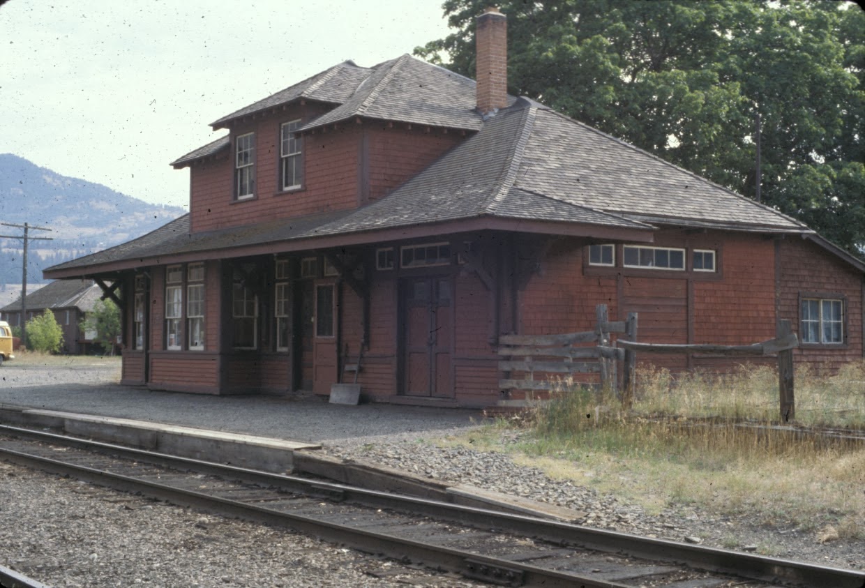
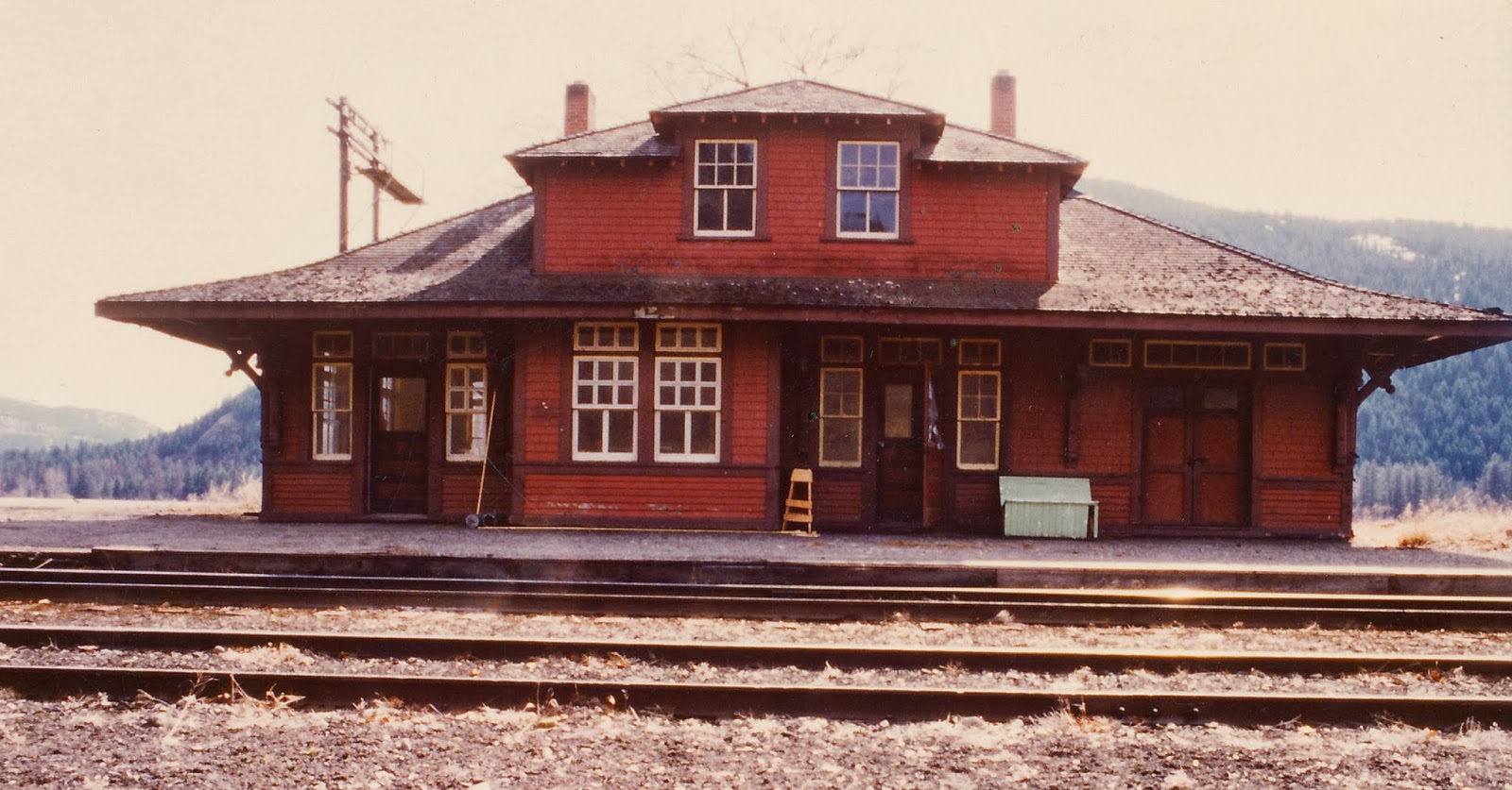
Midway was mile "0" for the Kettle Valley Railway and its successor, the Kettle Valley Division of the CPR.  This photo shows the well-preserved station building shortly after it had ceased to function as the local railway agency.  It is appropriate that the station serves today as the local museum because the railway played a significant role in the life and history of the town and the surrounding area.  This is a CPR Standard No. 5 Station which was very common in small towns throughout the west.  Prairie versions often had a significantly extended freight section next to the baggage room.  Individual stations varied in some of their details.

In today's post, we will provide some information and drawings for this handsome structure that the CPR erected in Midway about 1909 according to Joe Smuin's Kettle Valley Railway Mileboards.  The plans presented here were hand-drawn by Coquihalla Man in late 1984 from field measurements taken that summer.  The family were nice enough to indulge my request to accurately record the details when we stopped for a few hours on our way to a vacation in the West Kootenays.  We stopped on our way back as well for a few more.

Here is the Front Elevation with 2 critical dimensions for scaling your print.
Here is the East Elevation.  In this view, the East Annex is visible.  My guess is that this addition was made sometime later as the windows and trim are non-standard but the wall finish has been duplicated: drop siding, water table, sidewall shingles, corner boards.  Presumably, the station agent and his family were in need of more living space.  Another detail to note is the platform which in this view is a wooden one while the West end elevation shows a gravel version.  There is a published photo in Robert Turner's book (West of the Great Divide, p.270) showing a Dayliner at the Midway station with a planked platform in evidence, the details of which are shown here.  It has a slight fall or slope towards the track.  The height of the track relative to the platform is taken from CPR plans of other stations. 

Here is the West Elevation which shows another annex.  This time the wall finish is different than the main building and again the windows are non-standard, even differing from those of the East annex.  This suggests that this West annex is an even more recent addition than the other.  Note different positions of chimneys with respect to centre-line and front elevation as well as their different widths.   This elevation has details of the gravel platform that graced the front of the station in her latter days.  It would seem that a freight door was original to the station but at some point, it was boarded up - perhaps when the West annex was added on.
Here is the rear elevation.
In reproducing these drawings, measure between points on the building; e g, 50'-0" length, and try to get your computer print as close to 50 scale feet as possible.  Check for height as well.  Photocopiers will often distort heights one way and lengths the other.  The critical dimensions are:
  • length 50'-0"
  • width  21'-6" 
  • height 25'-0"
Downloading the plans and printing them in HO scale is not too hard.  I actually figured this out by myself.  Here is my method.  There may be other ways but this works for me on my H-P laptop.
  1. Copy plan image to a Word Document
  2. Click Page Layout tab
  3. Click Margins tab and select Narrow
  4. Click Orientation tab and Select Landscape
  5. Click View. Select Zoom This offers an enlarging or reducing percentage
  6. Take a sheet of 8 1/2" x 11" paper and hold it to computer screen, adjusting Zoom till length of Word Document matches 11" dimension of paper sheet.  In my case that is 105%.
  7. Click on image.  A border will appear.  Move cursor to lower right corner of border.  Click and hold on the tiny box, moving arrow diagonally down and to the right.  Release and allow image to stabilize.  This adjusts both dimensions of image.  You may have to move cursor off the page but that is okay.  The critical thing is to move the corners of the image on the diagonal.
  8. With a scale ruler measure the length of the building.  Move cursor and arrow diagonally outwards to enlarge.  Move cursor diagonally inwards to reduce.  Adjust till length of building matches 50' mark on scale rule.  The height should be in scale as well.
  9. Check height with scale rule.  Should be 25'.  If building image is too short or too high, you can adjust this to get it right without changing the length.   To adjust height only, place cursor on tiny box at bottom centre of border.  Click and hold, pulling the cursor down to stretch the image or up to shrink it.  By trial and error you can get this  dimension to be correct.  Everything should then be in scale and drawing can be measured for details.  This is amazing and so much more accurate than using a copier.
  10. Print and check dimensions.
The next post will present the floor plan and a photo of my model version with its complex though attractive roof line together with some modeling suggestions to produce this in scale.  Later posts will provide a station ground plan of Midway and a description of its facilities with modeling in mind.

See you next Wednesday.

Coquihalla Man


Wednesday, 19 February 2014

A MEDIUM DOUBLE TUNNEL PLEASE


Here is a shot that reveals some unfinished business and some mediocre lighting.  In a manner of speaking, this is a double tunnel.  The first part of the post discusses the reasoning behind this peculiarity followed by a basic description of the construction of our cast tunnel portals which we featured in previous posts.  We will conclude with some CPR drawings of one of the portals which hopefully you can download if desired. 
For the transition between the scene in THE TUNNELS post and the next scene, I decided on this medium double tunnel by which I mean that the tunnel through this mountain outcrop is actually a composite of the prototype's tunnels 2 and 3.  The east portal (right) is that of Tunnel 2 and the west portal (left) is that of Tunnel 3.  They are 1/2 mile apart in reality but the west portal opens up onto another scene that was very appealing for reasons we will discuss in another post.  Tunnel 3 is 272 feet long and this model version is quite close.  For the Coquihalla Subdivision, this is one of the medium-sized tunnels which ranged in length from 164 feet (No. 7) to 556 feet (No. 10) according to Joe Smuin's Mileboards.  In all, there were 12 Tunnels on the Coquihalla Subdivision most of which received the concrete portals starting about 1940 as the timber-framed originals required upgrading or replacement.  

The West Portal of the Tunnel with the three sections placed but not secured.  Some additional rock castings, gravel and greenery will be added to finish the scene.  The left edge of the portal fits into a slot cut into the rock casting, the cut having been made before the rock casting was installed.  Behind the portal, a cast plaster tunnel liner can be seen covered with the handyman's secret weapon - Duct-tape.  The liner is made in sections of two parts, each from a mold marketed by Woodland Scenics.  This facilitates removal of the rock tunnel linings for track maintenance.

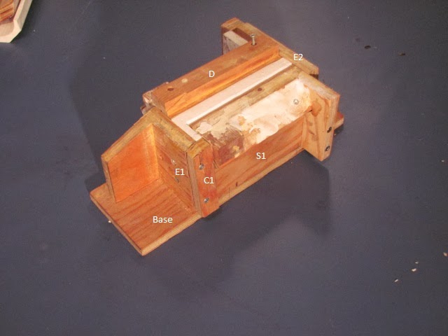
From field measurements, I drew up plans for the various portals and then built a wood form with which to cast them in Hydrocal plaster.  The form is portrayed in photos below. 

Key:
  • Base
  • E1& E2 = Ends
  • S1 & S2 = Sides
  • C1 = End Cap
  • D = Dam
  • T L = Interior Portal Lining
The Portal is cast in three steps resulting in three pieces.  A Left Half, a Right Half and the Lintel.  Here is the form with the right half poured and set.  This casting is the same as the right half of Portal No. 1 West and will be used for No. 3 West. From this one basic Interior Tunnel Portal Lining form (T L) and several different outside forms, many different portals can be cast. 

The Form stripped.

Note that S2 is in place simply as a holder for the Dam D, fitted to the centreline. The left side will be poured separately.  
The faces of all parts of the form have been clad in scale lumber.  Mostly 3 x 12's. For the arch itself, 3 x 6's.  Board lengths are 5 feet and 15 feet with joints staggered on 5 foot centres.  Total length is 45 feet from the portal face.  The form boards of the portal face (E1) align with the boards of the tunnel portal lining (T L).  All corners have a 2" chamfer which I make simply by filing the edges at a 45 degree bevel.

Before pouring in the plaster, all faces of the forms are liberally coated with a release agent - in this case Pam cooking oil from a spray can.


There is a very interesting photo of a prototype concrete form for a Kettle Valley Tunnel in Barry Sanford's Book, McCULLOUGH'S WONDER: edition of 2002.  It is found facing page 160.
 
Here is the CPR plan for the West Portal of Tunnel No. 1, Mileage 19.7.  It is in two parts for scanning convenience.  Its dimensions correspond closely with my field measurements.  Interestingly, such is not the case when comparing field notes and drawings for the East portal of Tunnel 2.


Close examination reveals that the centre line of the portal is offset from the centre line of the track towards the inside of the curve.  This offset increases as does the width of the portal, in proportion to the increasing sharpness of the curve.  This is something to bear in mind as we plan our tunnels on curves.  Not a bad idea to test for clearance with our 80 foot passenger cars or Big Boys with the very wide overhangs.  In the case of our double Tunnel, the curves are prototypical; thus, we were able to build the portals to scale.

I hope this is of interest and assistance in your model building.  I intend to publish more drawings in the future.  In fact some of the posts may be heavy on the drawings and photos but light on text in an effort to shorten the time involved in creating a post.  We will continue now with posting once a week on Wednesdays.  As to future posts, readers' response and requests are solicited.  Incidentally, I like my coffee black.

Coquihalla Man


Thursday, 13 February 2014

TUNNEL PORTALS OF THE MODEL KIND

In the previous post I described the adventure of the field work to record the features of the Tunnel Section of my layout.  Today we will look a little closer at the tunnel portals.  In a future post I will describe a few details of their construction.

Mileage 19.7  The West Portal of prototype Tunnel No. 1 is a bit worse for wear but still intact if the CPR would like to reopen the line!  A few scratches but still serviceable? -  maybe not.  They would have to muck out a fair amount of rock and gravel as the interior has completely collapsed.  The rock shed part of the portal extends 45 feet into the mountain as noted on the plans which the  Engineering Department of CPRail graciously allowed me to acquire from their extensive plan room back in the 1990's (now closed).

Evidently, all the portals and rocksheds of the Coquihalla were originally constructed of Wood Timbers but the CPR upgraded them to concrete in the 40's and 50's.  Even so, the interiors of the tunnels were often lined with 12" x 12" timbers called Tunnel Sets.   According to Joe Smuin's Kettle Valley Railway Mileboards, the tunnel itself was 218 feet long when the west portal was built in 1947.  The east portal was rebuilt in concrete in 1951.

Here is the model, the "concrete" looking fairly fresh as it would be only 2 years old in 1949, my target year for the layout.  By the time that I acquired the official CPR drawings, I had already built the portals from field measurements out of Hydrocal plaster. This ideal modeling medium was poured into a wood form to create the replica in 1:87 scale.

From the plans, I learned that the prototype tunnel was constructed on a 200 foot spiral to an eight degree curve but I had guessed wrongly that the track alignment was still fully curving as it left the portal.  I am glad that I proceeded with this engineering "inexactitude" as it turned out, because I think the scene actually looks better with a curve as can be seen in a photo of the previous post.  Besides, as zealous as I am for prototype modeling, it is too much to rebuild for what is a minor discrepancy.

Mileage 19.9  Now a photo of the East Portal of Tunnel No. 2.  The Prototype:


Both portals of Tunnel 2 were built in 1943 and the total length was 280 feet.  There was a 10 degree curve right as the track entered the east portal ending in a 200 foot spiral as it left the west portal.  Interesting colour in the rock.


And the Model:

That foreground gravel and rock is the real deal, collected from the slopes of mile 19.  However, the caboose is not constructed out of wood and steel from a real one.  Looks like we need a little more colour and some greenery to liven things up.  Plans and field notes should appear in a future post as well as a few details on how they were built.

 
I invite your comments and questions.  Not sure what the procedure is.  If someone knows, clue me in because I am new at this.

Coquihalla Man