Tuesday, 5 January 2016

THALIA TRESTLE IN HO - THE BRIDGE DECK Part 1

Well, it has been a while since our last post but here we are with a follow up to our study of the CPR pile trestle near Thalia, BC at Mileage 102.7.  This bridge was rebuilt several times over the years and we are modeling it with reasonable accuracy for the 1949 era.  We provide here some drawings with a few details and comments on how we built this miniature, focusing today on the bridge deck.  In preparing this post it must be said that it is not an easy thing to describe the construction of the model or the prototype and this is partly why we have taken so long to get to it.  As it is, this article will have to be broken up into several posts as it has already passed 2200 words.  Another reason for the long delay in posting is that we have been going through a major building boom on the layout with developments by the B&B gang, and the scenic and Rolling Stock departments.  And we assisted in making a motion picture of our operations which we will present eventually.
Much of the information presented here can be applied to other trestles of course, but this one has several features that are not usually found in the model railroad press: approach fills; a prototypical curve; a non-standard span to cross a roadway.  For this reason we will give some detail on its construction from actual CPR engineering documents and our model-building techniques.  To start with here is a photograph of our interpretation in HO scale of the Bridge at Mileage 102.7 on the Princeton Subdivision.


In considering a location for this bridge on the layout, we decided to make a small compromise in the overall length and number of bents.  There were14 bents in the photos and plans that we have presented earlier.  For the model, we felt that reducing that number to 12 would not seriously affect our reproduction in miniature.  All other dimensions and details are accurate.  Bridge Mi. 102.7 was one of numerous crossings of the Otter Creek between Tulameen and Brookmere which the VV&E and the KVR bridged with pile trestles for the most part though sometimes a frame trestle was constructed.  We count fifteen of them listed in Joe Smuin's book, KETTLE VALLEY RAILWAY MILEBOARDS.  They varied in size, some being a mere 30 feet long to the large one at Tulameen which is 334 feet long.  The subject of our study is some 200 feet in length but on the Kettle Valley Model Railway it has been shortened to 170 feet by eliminating bent Nos. 4 and 11. 

We did retain the obvious features of the road and creek that pass under the bridge which we found to be very desirable in that they suggest there is some civilization in the area.  For the most part, the Kettle Valley Railway traversed a landscape that was fairly remote and unsettled.


Unfortunately, our model plan of the Thalia bridge deck was rendered illegible during its construction but we can offer some prototype drawings and descriptions of the process.  Here is part of the drawing which was presented in a previous post on June 10, 2015.  The construction of the bridge deck was typical for our era for both frame and pile trestles.  This drawing shows a straight bridge deck but most of the detail applies to the curved trestles as well. 
Next is a detail from an actual CPR drawing issued on September 3, 1957 which shows how the stringers are laid out for a curved trestle.  The plan for the "E-50 Loading" seems to match the drawings for other KV Trestles in our collection.  For the sake of clarity, the stringers have been coloured.  The pink stringer (A) is the longest one at the standard length of 30' and it is beveled a little at the ends as are all the stringers.  On the full plan which follows, a table is provided which gives the lengths of the other stringers according to the curvature of the track.  For a curve of 8 degrees, Stringer "B" is 3/4" shorter than "A" at 29' - 11 1/4". Stringer "C" is shorter again.  However, in building our model we did not use these measurements.  We simply placed the model timber directly on the plan and marked the cut line with an X-acto blade and then sawed it to length.  The slight bevel on the ends of the stringers was made with a file.  On the drawing below, note how the joints are staggered and spacers placed as illustrated.  These spacers were made of wood for the model version.  Also note that stringers are butted to each other on the centre of the 12" bent cap so that they each have 6" of bearing.

Here is the full page of the CPR trestle plan issued on September 3. 1957.


As an added challenge to our modeling efforts, the engineering drawing in our previous post (and see below) calls for a superelevation of 2 1/2 inches for the eight degrees of curvature in the track as it crosses the bridge.  This, we are pleased to say, was accomplished in the model.  It is evident in the photo to the right that the caboose is listing somewhat and the cars ahead of it are progressively straightening to the upright position as the rails are easing out of the superelevation and of the curve.  Standard railroad practice for superelevation is accomplished by lifting the outer rail while maintaining the inner rail "at the established grade line".  This practice can be followed in our miniatures as well but this really is a small detail that some modelers might determine to be not worth the added complication, especially if the viewing angles render it not so noticeable. 

In a future post we will treat of superelevation in more detail.  For now we will point out the basic principle that as the curvature of track increases, the amount of superelevation increases and this applies to all track whether on a grade or on a bridge.  One other factor in determining the amount of elevation is sometimes called the "design speed".  This is simply the average speed of the different trains which use that track whether passenger or freight.
For our trestle, the plan calls for a curve elevation of 2 1/2" in 5 feet (see red arrow) which according to a table in one of our engineering books suggests that the design speed is 22mph.  The Kettle Valley was not renowned for its land-speed records.
Taking another example from the same table, we note that a sharp prototypical curve of 12 degrees (in HO about 65" radius) and a design speed of 22 mph, the outer rail will be 3 7/8" higher than the inner.  This would be quite noticeable.  However it is likely that a curve of 12 degrees would have a permanent slow order of about 15 mph, so the superelevation would be reduced somewhat.
One further point to add is that a transition from level rails where the tack is tangent, to the full superelevation is accomplished gradually through the curve easement (aka spiral easement; transition curve; or tangent lead-in).
To the right is a blow-up of the "NOTES" in the upper right hand corner of the general plan given above.  In the figure is the letter "a" which is the amount of tilt or superelevation.  The word "sprung" suggests to us that it was preferable to bend the timbers or use their natural bow on broad curves rather than use a bunch of spacers.  This would not apply to stringers in sharp curves as in our case study.

We will continue soon with another post on the construction methods we used in building our model of Bridge Mileage 102.7 on the Princeton Subdivision.

Good to be back;

Coquihalla Man

Thursday, 18 June 2015

BRIDGE 102.7 (THALIA)

The Bridge at Mile 102.7 is an interesting example of a C.P.R. Pile Trestle.  The example shown in the accompanying photos by Dave Love is the most modern version, the bridge having been rebuilt several times since first constructed in 1914.  We see the standard 15 foot spans but there is a unique twenty foot span towards the centre that crosses a country road.  Unfortunately, the span is somewhat obscured by the foreground trees but it is still a useful shot.  Regrettably, the trestle is no longer standing, as some cruelly irresponsible vandals torched it about five years after the rails were lifted in 1990.   Another interesting photo taken by Dave when the bridge was still in service was shown in the last post

The road runs from Princeton to Merritt; however, on our earliest drawing it is identified as the Nicola - Princeton Road.  The winding gravel road is still in use today for business and recreation.  Occasionally, cattle are seen wandering along the road as there is significant ranching conducted in the area.  There is also a small watercourse running beneath the trestle called the East Fork of the Otter Creek.
Next we see the other side of the bridge.  The creek is on the left of the road and we are looking roughly south.  Immediately apparent in this view is the extra wide span to accommodate the gravel road. 

We had the good fortune to ride over this bridge in the way freight shortly before abandonment in 1989.  There was a permanent slow order here due to some bad track in the long curve leading to it.  The train crew said that this was the only bad track on the whole 177.8 miles of the modern era Princeton subdivision.

Here is the original Station Ground Plan with some identifying labels inserted by us.  The original was drawn in the plan office of the V. V.& E. likely around the time of construction.  The Trestle is identified as BRIDGE No. 543.
Numbers refer to features as follows:
  1. Cinder Platform - Thalia "station"
  2. East Fork Otter Creek
  3. Nicola - Princeton Road
  4. Car Body (presumably a sectionmen's bunkhouse)
  5. Tool House
  6. Section (Foreman's) House (24' x 22')
  7. W. C. (Privy)
  8. Headblock of East Siding Switch

Next is a close-up of the bridge area from the drawing.  V. V. & E. practice was to show two lines for the track whereas CPR practice was to draw only the centre-line.  The original bridge was a Frame Trestle of 15 Bents according to the drawing.  Later rebuilds possessed only 14 Pile Bents as will be seen in later drawings.  When the fill approaches were originally done it appears that the creek underwent a diversion or "channel change".  The trestle was built on the 8 degree curve .  Note the Section House which was standard Great Northern design and its outhouse.  Ironic that the outhouse was designated a "W.C." (water closet) when of course there would not have been any running water within.  The remains of a small structure are still to be found in the high grass in this area.  This looks to us more like a root cellar built partly into the hillside which was common enough in the early days before the modern convenience of refrigeration.  Joe Smuin, in his book, Kettle Valley Railway Mileboards states that the house was removed sometime before 1953.  Note also the Flanger signs either side of the Bridge.


We include another drawing which is not essential to modeling but may be of passing interest to readers. This is a small portion of the Grade Profile Roll from a much later era which shows the bridge in question.

We will try to interpret some of its features.  Typically, the centre portion has the vertical scale exaggerated for clarity.  First we see the identifying label: A BRIDGE 102.7 and 14 PILE BENTS.  At the top we see a straight line B with the bulging section depicting the unfolded plan view of the bridge.  The line is straight but directly below at the bottom is the indication C 8 CL that the bridge is on a curve of 8 degrees left (when looking West).  The grade at
this point is 0.88% rising westward to Brookmere.  In the middle is a sloping line D, and a schematic drawing E of the bridge showing the 14 bents.  The "X" marks suggest the longitudinal bracing and the bridge has two stories.  The wiggly line F crossing and recrossing the sloped Grade line is the original grade of the soil as found on the centreline of the track when the railway was first built.  Of course the high spots were brought low or cut through and the low spots were filled in.  On either side of this trestle, long fills were placed at the approaches.  The low point to the east of the bridge schematic may have been the original bed of the Otter Creek which we know from another drawing was filled in and a new channel for the stream dug near the road.  At G is a number (2825) and line which represents the elevation in feet above sea level.  The short heavy line nearby represents a culvert designated 24" C.M.P. which could be a 24" Corrugated Metal Pipe.  The circle with the number 103 is the milepost measured from Penticton.

This next drawing is presented in two parts and should be very helpful for modeling purposes.  This view shows the profile of the bridge.  It is dated 1956 and 1962.  The E-60 inscription denotes the Engineering standard of this bridge which is heavier than an E-50 which was more typical of the 30's and 40's.  There are more piles per Bent and heavier bracing.  Stringers may be heavier as well.


Note that the bents are numbered from east to west which is the usual engineering practice for the CPR.  The twenty foot span requires heavier timbers for the stringers.  The increased depth of the stringers (26") is accommodated by setting adjacent bent caps lower by 6".  The adjoining standard stringers (20" high) are shimmed up with 6" packing pieces to make up for the difference in depth.  We do not posses a photo that shows this clearly.  The longitudinal bracing of the elevation drawing crosses alternate bent spaces but the photo at the top from modern times shows every bent space braced.  To the lower left are found the details of the Ballast Wall or End Bent. One photo from the 1940's shows an even different bracing pattern.

Here is the second part of the drawing which shows each of the other bents in greater detail and the title block.


Note the tilt of the bent caps to provide for the super-elevation on the 8 degree curve.  This is a challenging but effective modeling detail to incorporate if possible.  Bents 8 & 9 have 8 piles to give extra strength for the twenty foot span.  The placement of the 6" x 8" Girts and 3' x 10" cross bracing are shown here.  Not shown is the table of "Penetration of Piles".
From this drawing and a few photos we built a fairly accurate model which will be presented in our next post.

Until then...

Coquihalla Man

Wednesday, 10 June 2015

C P R PILE TRESTLES

We begin a series of articles on Trestles as used on the KVR and CPR.  We will treat of a few trestles as originally built for the KV and, in addition, some rebuilds of the 60's, but most of our posts will concern trestles of our modeling era of the 1940's and 50's.  There were significant differences in the construction of Frame Trestles in particular through the decades of the twentieth century.  On the other hand, the details of pile trestles did not change so much and these will be our focus for this post.  And again it must be stated that we write from a modeler's perspective.

Pictured here is a pile trestle of more recent vintage as it existed late in its service life.  This fine shot was taken by Dave Love who has kindly allowed us to post it.  Sadly, some local vandals burned it down shortly after the steel was lifted.  Some of the charred pilings are still standing but little else remains.  This is the bridge at Mileage 102.7 of the Princeton Sub.

Pile Trestles take their name from the Piles or peeled logs that were driven by a pile driver into the ground until bottom was found or sufficient penetration was accomplished to satisfy the Engineers that they would not move.  These piles were 12" to 14" in diameter and of course somewhat tapered as nature designed them.  They were a high grade of log and normally peeled of all bark and then saturated with Creosote.  When all the piles of a Bent were driven, the tops were cut off in line and pins were driven into the tops of the piles.  A Cap with mating holes for the pins was placed on top of the piles and the whole bent braced. 

Next is a close-up of a different pile trestle, some details of which are identified to illustrate further the drawings which follow.  The Bulkhead timbers are nailed to the pilings of the End Bent or Ballast Wall and to the stringers to contain the fill material and ballast of the track leading up to the trestle.  The timbers are 3" x 12" s stacked on top of each other in progressively longer lengths though there appears to be a fourth 3" x 12" whereas the drawing shows only three.  Stringers were set in pairs over the Bent Caps, there being three pairs in all.  Each Stringer was 30 feet long so as to span two bents.  For each pair of stringers, the joints were staggered over every second bent.  A Spacer separated the two stringers of each pair and Bolts passed through the stringers and spacer.  The Bridge Ties were nailed to the outer stringers with 14" Lining Spikes.  In addition, 3/4" Bolts were passed through some Ties, through the space between the outer pair of Stringers and through the Bent Cap.  The (Outer) Guard Rail is a 5" x 8" timber which is spiked to every Bridge Tie in an alternating pattern.  In later construction a galvanized iron flat bar became the norm.

To make an important distinction, there is an Inner Guard Rail that is the extra pair of rails which run the length of the bridge.  These rails keep derailed wheels from wandering too far, hopefully preventing the cars from leaving the bridge.  The metal Connector Plate that ties the Stringers to the Bent Cap is a "modern innovation" to replace the 4" x 6" blocks of the earlier style construction.  These blocks were still in use on the Tulameen bridge shown here and in the first photo above.  The through bolts tying the stringers together are visible here.

The Mileboard Sign is attached to the end bent which is not the usual practice but this is a very short bridge - only 45 feet long.  Normally, the mileboards were placed in the centre of the bridge on the engineer's side when facing east.  The bridge timbers and the Creosote look quite new at the time this photo was taken and we speculate that his bridge was built in 1972 according to one of the notes on the grade profile drawing.  According to this drawing, it seems that before this short trestle was built, a culvert and fill was in place here from at least 1963.  But there are several erasures and notes at this location on the drawing and we cannot be definitive about our interpretation.

On the extreme right is the edge of a Water Barrel available for emergency fire protection.  Placement on the bridge approach was the practice when trestles were short.  On longer trestles, a refuge and Platform were constructed at intervals along the bridge itself as seen in the first photo above.

Here is part of a plan that we drew from original C P R drawings which dated from 1941.  It is a lighter construction and Engineering Standard than the one in the photo with one less pile per bent.  The more piles the higher the rating of the Bridge in terms of load bearing.  This was the standard of the day.  One other item to point out is that pile trestles of the 1950's and later, for the most part had their outside piles "Battered" i e, sloped outwards whereas the 1941 drawing specifies that the piles were only battered on trestles over 20 feet in height.  Both trestles pictured above have this feature. 

 Here is the other part of the plan, showing the bent construction.


When driving piles, they do not necessarily go in absolutely straight and plumb.  Sometimes adjustment must be made for this and for the piles being somewhat thinner or thicker in diameter at the top where the cap is placed.  These irregularities are accommodated by shims and notches as shown here in detail shots of the Tulameen trestle.


These two photos show the Sway Braces that most bents possess.  They always run diagonally from the 2 o'clock position to the 8 o'clock position on each face.  They are cut from 3" x 10" planks and are through-bolted at least at the ends and often on each pile.  Or the sway braces are simply nailed to the intermediate piles.

And sometimes the Bridgemen do not cut the pile tops accurately enough so that shims must be placed between the top of the piles and the caps.

Next post will deal with an interesting example of a Kettle Valley Pile Trestle.

Till then...

Coquihalla Man

Sunday, 31 May 2015

HAPPY BIRTHDAY KVR!


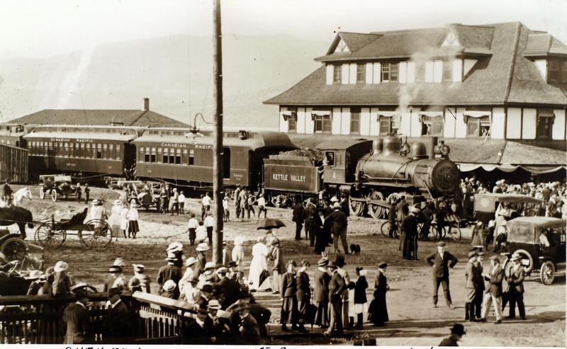
large photo One hundred years ago on May 30, 1915, the first passenger train arrived in Penticton to much fanfare.  This was the first of many trains to run on the Kettle Valley Railway which had a most important hand in developing the interior of British Columbia.  Sadly as we all know the railway did not last forever but there continues an abiding interest in all things KV. 

This image is courtesy  of the Okanagan Archive Trust Society.  Other photos of this auspicious occasion may be viewed on their website at:

 http://www.oldphotos.ca/archivos/collection.php?collectionID=2&folderID=920355238


Most probably "Passenger Extra 4 East" ran on rails that crossed a fair number of trestles spanning small creeks
 
large rivers and gorges

 on its way to the Penticton station.

These wooden trestles will be the subject of our next series of posts.  They will cover CPR standards for both pile trestles and frame trestles of the 1940's and 50's.  We will deal with the the appropriate details for the modeler such as the trestle deck, bent construction, bracing, girts and cribbing.  Dave Love kindly allowed us to share these wonderful photos of the Myra Canyon trestles which he took when the rails were still in place.

But for now a celebratory note must be sounded.  Happy Birthday KVR!

Coquihalla Man


Wednesday, 13 May 2015

BROOKMERE ROUNDHOUSE IV: A MODEL IN 1:87

The second enginehouse in Brookmere was destroyed in March of 1949.  The CPR decided to rebuild it fairly promptly and the plans show a date of July 11, 1949.  This post will treat of the model constructed from the CPR drawings and some field measurements of the foundation which were taken about 1986.

First we will supply some additional information to supplement the preceding post in the interests of aiding modelers to construct miniatures of this fairly plain but still interesting four-stall wood-frame enginehouse.  There has been a significant delay in composing this post and this is due largely devoting hobby time to bringing our model to completion.  Well, "completion" except for the doors which are "back ordered".  The Stanley Cup Playoffs have been something of a distraction as well.
 
Here is a view of the actual Brookmere roundhouse foundation.  The engine pits and other bays have all been filled in with gravel.  The pit stalls still retain their rails which were bolted to the concrete using 1 1/2" nuts and 3" washers spaced 12" apart on each side of the rail.  The two outside bays were fitted with standard ties and rail when the enginehouse was in service.
This next photo shows the turntable pit and enginehouse foundation as built in full scale for our Brookmere shop area.  Basic dimensions are provided from field measurements.  These can be compared with the dimensions on page 1 of the 90 footer plans published in the post of March 28.  It appears that most major dimensions of the 90 footer are common to the 100 footer except for three critical items: the length (naturally); the width of the rear walls; the distance from edge of turntable pit to front wall.  The site measurement of this last item is about a foot longer than what the plan of the 90 footer calls for.

In laying out the foundation for the enginehouse, one important consideration should be the relation between the three dimensions mentioned above.  Any change in one will affect the other two.  One non-variable will be the width of the front walls, each of which is made up of a pair of doors 6'- 6" each and part of two 12" posts.  This overall dimension is 14'- 0" for each front wall.  Another non-variable is the location of the house tracks.  Where they converge at the edge of the pit, there must be some distance between adjacent rails to forestall the possibility of a short circuit.

Note in the photo and in the page 1 plan, that all lines of track centres, walls and partitions (i e, line of post piers) between stalls converge on the centre point of the turntable.   The front and rear walls are constructed at right angles to the track centrelines.

This view shows the interior framing of the house and the colours that were based on the coloured photos by Glenn Lawrence, copies of which were provided in the previous post.  The interior blue is a custom blend of Floquil paint, the formula of which has gone from our memory.  This is intentionally a bit lighter than the exterior wall colour.  As on the prototype, the interior is quite dark when the roof is in place.  Since the prototype and the model will not have the luxury of electric light, it was thought that giving the walls a lighter shade would help the detail be seen better by the full scale viewers.  We are thinking of setting up a few tiny "kerosene lamps" (using the nano LED's) amongst the stalls to represent the illumination of the period.
The paint used for the upper walls and roof timbers is Floquil Antique White.  One of the walls is masked up for painting.  It takes a few hours to get the masking right as the tape must be fitted so closely around each of the studs to prevent over-spray of the dark blue to work its way into where it should not be.  The painting itself is done in a matter of minutes but the finish is infinitely better than painting by hand with a brush.

The colour chosen for the foundation and floor is Floquil Concrete.  The length of the engine pits is based on the site measurements.  They are 6' - 2" in from the front of the foundation and extend to the end of the track.  The foundation and floor is made entirely of Evergreen Styrene.  The manufacturer of the piers is unknown but they match the field measurements and are simply glued on top of the floor.  As will be described below, tapered holes were drilled and rasped out after setting in place.  They were carefully laid out with dividers to get them accurately placed.  The hoods of the smoke jacks can be seen on the underside of the roof.


These two shots show the lowering of the house into position with the pins "entered" into the sockets in the concrete.  Getting the pins to enter takes a bit of patience but by going slowly and working from the rear to the front, it takes only a minute or two to get them all in and the house settled.  The time taken to make the building demountable is well worth it since the track is accessible for maintenance purposes and for further detailing. The engine pits meed stairs and bolts for the rails.  The workbenches, tools, jacks and supplies associated with locomotive maintenance will also be added to give the house a lived in appearance, but for now we are just glad to have the structure proper completed.

Each of the piers has a hole to receive the pin of the post and this hole is tapered so that it is wide at the top and narrow at the bottom.  This facilitates the pins entering easily and then as they progress down the hole to the narrow end, the posts are pulled to the centre of the pier.   The pins are centred on the post.  The holes in the foundation wall are also tapered.  The taper is cut with a Dremel tapered rotary rasp after drilling a pilot hole on the centre of the pier.  Having an opening in the roof is helpful for tweaking the posts' pins into position over their respective holes.  It also provides an interesting view of the interior that is hardly visible from any other angle.

A shot of the enginehouse from the rear, showing the smoke jacks and ventilators.  The colour of the jacks and ventilators is based on their appearance in the 1968 Glenn Lawrence shot.  At that point they had endured 19 years of weathering, so what they looked like when new, is uncertain.  The specifications detail a fire retardant paint but colour is not specified.  The removable roof section is obvious from this angle and a solution to the protrusion must be found.  Perhaps weighting the section will do it.


The roof was constructed of 0.030" styrene sheet bonded to the Purlins and walls.  To it was glued a layer of garnet sandpaper to represent the tar and gravel of the plan specifications.  No photos reveal the real roof and its colour. The sandpaper is 120 grit and its texture is a fairly convincing H O scale gravel when painted with Floquil paint: S.P. Lettering Gray.  Of course, gravel comes in whatever colour local pits supply and this is our decision after trying several different colours.  The fascia boards are 2" x 8" styrene and were painted before application.

Here is a drawing that is difficult to read of one more detail but could be helpful.  The overall dimensions are "about" 3'- 0" x 3'- 2".  The base is "about" 1'- 9" x 1'- 11 1/2".  Estimated height is 2'-8" above a flat roof.
One significant challenge was to find a suitable colour for the exterior of the enginehouse to approximate what appears in the Glenn Lawrence photos.  It is unmistakeable that there is a blue tint to the CPR "gray".   There were many attempts with different manufacturers' products including custom mixing, but our final answer is Tamiya paint: Sea Blue, XF-17.

This brings up an interesting dilemma for us regarding weathering and ground cover.  By our target date of September 1949, the building may well have been still undergoing finishing touches so, strictly speaking, weathering would not be appropriate.  But it seems so unusual by today's standards of model railroading to leave the roundhouse in pristine condition.  Just how much should we show as evidence of the iron horses inhabiting their stable?   We are inclined to ignore the historical constraint and do a little weathering but until we do decide, your comments are invited.

Monday, 20 April 2015

BROOKMERE ROUNDHOUSES, III

In March of 1949 the engine house in Brookmere was destroyed by a boiler explosion.  The young watchman on duty had made a most unfortunate mistake that cost him his life.  A photo of the wreckage has been published in Joe Smuin's  Canadian Pacific's Kettle Valley Railway, published by BRMNA, p. 28.  On the following page of that book is a photo of the third enginehouse which is the subject of today's study.  Bear in mind that the information provided here is, in the first place, for the benefit of the model railroader who wishes to construct accurate models in the style of the Kettle Valley and Canadian Pacific railways.  Of course, others are welcome to enjoy the photos, drawings and commentary as well, but our focus is helping modelers with accurate information.  We do get a few requests for specific info from time to time and will respond as much as possible both privately and in the actual posts.  This series on Brookmere is due to several requests and since we have a fair amount of detail on the railyard and facilities, the series continues.

Here is a photo of this third enginehouse taken by the late Glenn Lawrence in 1954, a mere five years after construction, apparently seeing little use with the coming of the diesels.  It is 100 feet long compared to its predecessor which was 10 feet shorter.  Comparing the two is interesting as they have many details in common.

Another shot by Glenn of the house and turntable has been published already in the post of March 5th.  Thanks to a friend John G., that post has an updated photo which is an improvement over the one originally published: http://kettlevalleymodelrailway.blogspot.ca/2015/03/cpr-70-half-deck-turntable.html
What follows is a series of photos taken by Glenn on his trip a number of years later, in 1968 shortly before demolition and salvage of the structure by a local resident.  The house had sat unused for several years by the time of Glenn's trip.  They are taken from a modeler's perspective and so are valuable for us modelers.
A full side view:

 The plan from 1949 in two parts:


Note the red X at the rear of the roof.  This is another example of the actual structure departing from the plan.  Comparing the plan with the photos of the side we see that the last 5 feet of the roof has an increased slope to the main roof.  This is effected by removal of the last purlin (a.k.a. rafter) marked by the "X" and laying the roof members directly on the top plate of the rear wall.  See also the drawings of the second (90 foot long) engine house in the previous post.
 
Here is the front half of the drawing.


Another divergence from the plan is seen when noting the placement of the windows in the photos. Other differences will be seen when comparing the interior framing in the photos and drawings.
Here are some shots of the interior.  These are rare and very helpful for the modeler.

Looking to the rear:

Post and Beam framing detail:
Looking to the front doors.  Note there are two fire hose boxes mounted on the posts (only one visible in this shot) and painted bright red.  There is a water supply pipe beneath the box.
This shot of the smoke jack is an interesting detail that is rarely seen. See also the previous post for dimensions that should be very close.

The exterior detail of the smoke jacks.  Note also the fascia board on the rear with the roof overhanging it.  On the front and sides, the roof had a fascia board projecting above the tar and gravel.  See the plan detail in the previous post.
A window close-up; this one of the rear wall:


The rear wall:

The main doors and upper front wall detail.  The drawing from the previous post is included for convenience.


Finally, two shots of our scale reproduction before the roof was completed.  Doors and fire hose cabinets still to be built and installed.  Styrene used throughout.


Until next time...

Coquihalla Man