Tuesday, 18 January 2022

A VIDEO

 A short video of the layout was published recently by a modeler friend, Burr Stewart of Seattle.  He has been doing a lot of good work these last two years to promote the fine modeling of the modelers of the Pacific North West.  His efforts have helped many a modeler to retain their sanity and to get through the drudgery of the restricted life forced on us by the Pandemic.  The raw video was shot during an operating session some years ago.  He contacted us seeking permission to work up a presentation of the layout with the footage he had taken.  We readily agreed and are pleased to provide a link here to the finished work. Part 18 - Canadian Pacific RR action on the HO Kettle Valley Subdivision of the "Southern Mainline" - YouTube

The footage is surprisingly good considering that it took place during an operating session where he was actually working several trains. Sessions on the KVMR demand attention to the job in hand so Burr did miss one or two small things on his assignments as he mentions in his commentary.  Nevertheless, we are glad he did pause to record the event as the video turned out well.

One of the trains he ran was Extra 3628 West, the mine turn out of Brookmere to Princeton which is a popular choice of assignments for those who like switching.  Here is seen lifting the loads out of the Tulameen Collieries spur.  He will then set out the empties and continue on the return leg of his assignment.  On the upper level a short way-freight is holding the siding at Iago for a meet.

 He also ran a Passenger train, No. 11, the westbound Kootenay Express which is seen crossing the Tulameen Bridge at Mile 71.7. Towards the end of the video he is piloting Extra 5783 East across the Bridle Veil Falls Trestle on the Coquihalla Subdivision.  Between assignments, he was able to shoot a Westbound freight, No. 79, transiting the upper canyon which happens to have in its consist, the cars he had previously set out at Coquihalla summit from his earlier mine turn.

 Burr's efforts make us realize how much we need to do more filming of the layout in operation as it is quite interesting.  This will happen eventually, but right now the project in hand is a major expansion of the layout to include about 45 feet of mainline on each of the two levels.   Details to come.

Coquihalla Man


Tuesday, 15 December 2020

LAST OF THE D-9'S ON THE KETTLE VALLEY

CPR Locomotive 592 of class D-9c was built in 1903 at Scenectedy Locomotive Works along with sisters 560 - 597.  No. 592 was most likely a mainline engine for her early years.  We do know that she was assigned to the Kettle Valley Division at least by 1947 where she served for a few years until moving on to spend her last days in the Western Region before being scrapped in January 1955.  Many D - 9's worked the Kettle Valley in earlier years especially on passenger trains Nos. 11 & 12.  A beautiful shot of 572 in the 1920's appears in Sanford's Steel Rails and Iron Men on page 82 and another of 579 on page 94 both of which are seen to be working passenger trains.  Engine 578 was the pusher on the infamous Jessica wreck of 1926.  The Smuin collection has a photo of an unidentified  D-9 as tail-end pusher on an eastbound freight cresting the Coquihalla summit.

A photo in our archives is inscribed "1950 Penticton R. M. Sutton Photography".   Another photo identifies her in Lethbridge in 1949 and another in Calgary in September 1952.  The Engineman's Time Book of R. E. Osborne, twice records her running as an extra on the Merritt Sub in May 1948.  Bob ran several of her sisters on the "Jitney" to Spences Bridge and back: 572, 573 & 586, all in 1948.  At one time or other, they all worked the Osoyoos branch as well as No. 569.   Engine 572 also worked the Penticton Yard again with him at the throttle in 1947.  By early 1950, they seem to have been displaced by the D-10's: 914 and 925.  See an earlier post on them here: http://kettlevalleymodelrailway.blogspot.com/2019/

Here is the Sutton photo in what certainly is the South Okanagan.  (You can click on any of the photos for a fuller screen picture.)


We have several other photos of her and many more of her sisters from on-line sites, notably Old Time Trains: http://www.trainweb.org/oldtimetrains/photos/cpr_steam/D9.htm

Here is another of 592 from the BC Provincial Archives dated 1922 with original tender.


The late, Lance Camp was particularly fond of the D - 9 locomotive and had a model built by craftsman, Herb Mason of Victoria BC some years ago.  Their starting point was a model of a Northern Pacific Railway Ten-wheeler, the prototypes being built by Schenectedy about the same time as the CPR class.  His admiration was contagious which made the author consider acquiring one for the Kettle Valley Model Railway.  Happily, a friend was moved to offer gratis the very model that was needed to effect the rebuild.  Thank you Arizona Jack for your generosity!

Here are photos of the NP Ten-Wheeler model.  The sloping cylinders were a vitally important feature of the "starting point".  Apparently, versions of the NP model have been produced by several manufacturers over the years.  Ours is from the PFM run of the 1970's.


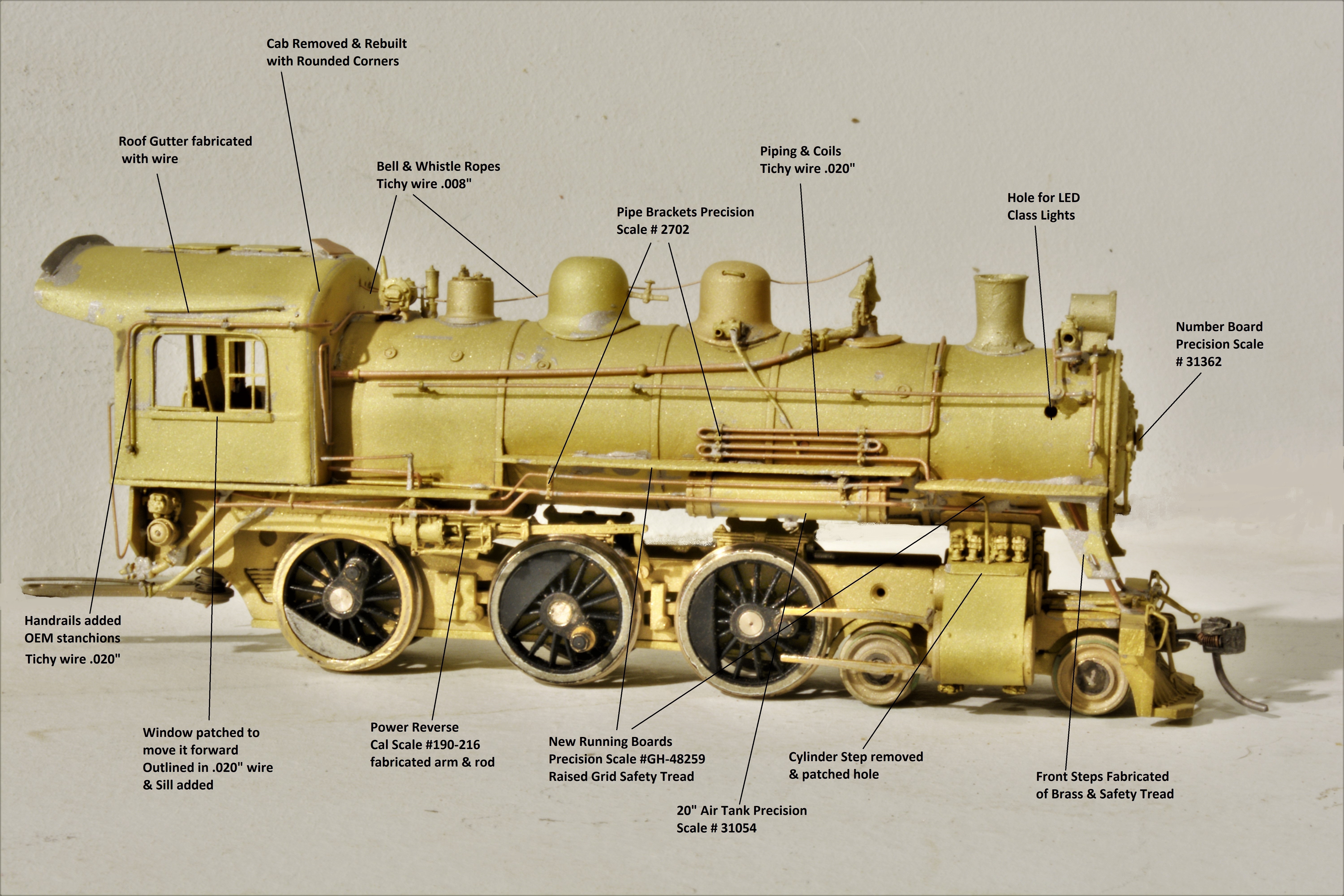
The first step we undertook was to strip the boiler of all appliances and rails and piping.  The photo shows the stripped boiler and at this point new handrails and running boards are already in progress.

The cab came off in pieces simply by bending the components with a pliers to break the original solder joints.  A length of square brass stock was soldered to the inside of the front of the cab after which the roof/sides were then soldered back to the front and rear panels.  With superb Italian and Swiss files in hand, we worked the front corners to shape according to photos of the prototype.  These files and other fine tools were obtained from our Local Vancouver supplier Lacy West Supplies Limited: https://www.lacytools.ca/Articles.asp?ID=1

The cab work was not the most challenging step in the process.  Re-setting it back on the boiler was straight forward enough thanks to our electronic resistance soldering unit.  There are several makes and models offered; ours is this one by HOTIP which we acquired secondhand at a very reasonable price.  Normally they run upwards of $400.  This unit is not to be confused with a simple soldering station.  A very good tool for brass work. https://www.p-b-l.com/pbl2002/hotip.html

Here are before-and-after shots of the cab.  Note that the window opening has been moved forward by patching and filing.  The window sashes had been removed and later were re-installed.

The front doors and windows have been framed with a beading of .020" wire.  Unfortunately, the doors are a little lacking in height but we did not deem the shortcoming serious enough to warrant a complete re-working.

The window opening needed a sill.

The handrail stanchions were saved and moved to their new positions with .020" bronze wire as handrails for the engine crew. 


A gutter and roof hatches were added later.

One very challenging step was forming and soldering of the new fin for the back of the roof.  This step required cutting, heating and bending the brass strip in a compound curve.  Not the best execution by our shops but "good enough".


 For those of you, our fellow modelers, who are interested in the detailing of CPR steam locomotives, here are two diagrams showing the detail parts used to replicate this prototype.  The most challenging single item of the project was the fabrication of the front steps at the end of the running boards.  Even with the use of a jig, the steps would fall apart while soldering in another area.


These photos were taken after washing and then sandblasting the model which was painted soon after that to avoid the onset of tarnish which can affect the paint finish.  The sandblasting gives the paint more "tooth" to adhere to the brass.  This is important for the KVMR as the locos receive a lot of handling since it is a "working" model railway.


Paint used was Scalecoat Warm Black and decals by Black Cat.  Weathering chalks provided by Bragdon Enterprises.

The class lights had been drilled out for LED's prior to mounting.  A hole was drilled into the boiler at the level of the junction box mounted on the handrail and after painting, the LED's inserted through the hole from the inside of the boiler.  The wires were fed into the bottom of the class lamps and then affixed in place with canopy glue  This also helps in preventing short circuits with the wires to the boiler and fixtures.  The hole then filled with putty and painted to match the smokebox.

We fitted the rear axle with a cam by Grizzly Mountain Engineering and mounted a wiper on the bottom plate to accept the cam wire from the TCS WOW Sound Decoder.  The decoder and Keep Alive were mounted in the tender and TCS connectors fitted.  We have abandoned Soundtraxx Tsunami decoders mainly due to the lack of a cam wire option.

As received, the model was equipped with a Mashima motor, a torque arm, and a Boo Rim gearbox.  These performed well enough but a new motor was changed-in with a double shaft in order to add a flywheel to the mechanism.  The torque arm was an obvious after-market addition and was fitted nicely.  The arm was attached to the gearbox with two 2.0 mm machine screws.  The drive-line universal coupling was a short section of model airplane fuel line connecting the motor shaft to the gearbox shaft.  This is also standard treatment for most KVMR locomotives.  The motor was simply attached to the arm with very sticky double-sided tape.  This motor and torque arm unit was likewise attached with double sided tape to the chassis.  We replicated this practice with the new motor and torque arm and found it largely eliminated any transmission noise.  The locomotive runs well at low and high speeds. 

A final shot of the Kettle Valley Division's D - 9c Ten-Wheeler shows her somewhat neglected condition as she ekes out her last days of service.  Actually, the weathering seems more extreme in the photograph than under the lights of the layout room.  But the many details of the locomotive show very well here.  No doubt she will work the Coquihalla pusher job once operations resume on the Kettle Valley Model Railway but other assignments could be made.


In closing, we can offer a word about why we chose 592 in particular to model of the several that worked the Kettle in the last years: she is one of the few of her class to retain the high mounted headlight and remained fired with coal.  And note that the tender is not her original one.  We hope to build an interesting as-built tender one day for aesthetic reasons but for now she has a standard 5,000 gallon tender from class N-2a consolidation - just like the real one in her last days.  Several details and modifications have been added to this tender following prototype photos.

This project has occupied most of our modeling time under the months-long Virus restrictions and we are very pleased with the results but it will be more than a few months before another brass project is undertaken. 

Coquihalla Man

Tuesday, 25 August 2020

STATION MILEBOARDS

The practice on the Kettle Valley Railway regarding Station Mileboards will be treated here and a few suggestions as to their fabrication in miniature.   Our first photograph is of a typical Mileboard on the Kettle Valley; this one for Rhone on the Carmi subdivision.  Dave Love would have taken this in the 1970's before abandonment and track removal in 1979.  The track looks a bit shiny so this photo may even predate the last trains in 1973.

As might be expected, a Mileboard sign was erected about one mile distant from a station that was listed on the Employee Timetable whether that station had a physical building or not.  Theoretically the distance was one mile from the centreline of the station or from the centre of the passing siding.  The purpose of the Mileboard was to advise the engine crew of the distance to the station which seems to have been more than one actual mile of 5280 feet.

This is our conclusion after an analysis of Grade Profiles in our files of CPR documents.  In the following portion of the Grade Profile of the Coquihalla Subdivision, the reader can see that the west Mileboard sign was located at about Mileage 19.2 whereas, Coquihalla station was located at Mileage 18.0.  Hence, the distance from the Mileboard to the station is actually closer to 1.2 miles.  The vertical lines on the drawing are spaced 1000 feet apart in the original scale of 400 feet to the horizontal inch.  The original vertical scale is 20 feet to the inch so as to more explicitly illustrate the grade and sundry right-of-way details.  The circled number 127 which is crossed out represents the mileage from Penticton set up in 1916.  The new mileages starting at Brookmere were adopted in April of 1940.

There were two other reasons for the Mileboard.  A very important purpose was that the Mileboard served as the Yard Limit sign according to what was told to the author by two KV men at the annual Brookmere camp-out some years ago.  Even though the CPR had a standard yard limit sign, there is but one "living" example of it to be found in the Midway museum.  Other than that there is little photographic evidence to contradict their statements.  At this time we are not persuaded either way on the use or non-use of the Yard limit sign.  But we digress...

Where there were yard limits for a station on the CPR, third class, fourth class and extra freights would slow to restricted speed because there could be another train within the yard limits.  This was not the case for the KV station of  RHONE because the Timetable did not indicate that there were yard limits as seen in this excerpt from the Timetable of April, 1949.  Rhone simply had a passing track of 35 car capacity.  No other operational symbols to note.


Unlike RHONE, the next station to the west, WESTBRIDGE, did have yard limits, the letter "Z" appearing on either side of the station name.  No doubt, the yard limits were designed to allow for wayfreight switching of the local industries which were mostly shippers of forest products.  According to Smuin, WESTBRIDGE had a station building and an agent to handle the local business.  Even though an agent was assigned here, the station did not rate a call sign and thus no train order board.  The agent would still be in communication with the dispatcher by telephone and and be able to offer telegraphic service to the local community.  The Timetable also shows that a water tank (W) was situated there.

Further down the list, is the station at BEAVERDELL at mile 42.3.  This station had an Agent for the local customers who were mostly in the lumber business and the Highland Bell concentrator whose loading ramp is off to the right.  We dealt with Beaverdell in a previous post here: http://kettlevalleymodelrailway.blogspot.com/2014/05/beaverdell-and-highland-bell.html  

The tiny building also served as a Train Order station as indicated by the call sign "BD" in the Timetable as well as by the Train Order Board in front.  The photograph was taken by David Davies in 1966 whose vast collection was acquired by the University of Northern BC.  It is well worth a visit.  https://search.nbca.unbc.ca/index.php/david-davies-railway-collection

 Note on the left side of the Beaverdell entry on the Timetable, the letter "D".  This establishes that the Operator was on duty only during the "DAY", i e, normal business hours.  The fact that BEAVERDELL was a Train Order station has meaning and relevance to the Station Mileboard - even in model operations.   RULE 14 (m) specifies that a long blast of the whistle must be sounded "one mile from train order offices..."; consequently, an engineman would sound the signal at the station mileboard.  This signal would alert the agent to the approaching train (should he perchance be "resting his eyes") and he would turn out to "PK" the train as it passed his station.

Regarding the specifications of the Mileboards we reproduce here the reproduction by Just IMAGINE Printing of the CPR standard drawing for the Station Mile Board.  It is far more legible than the original in our files.  Thank you Just Imagine Printing.


Here are our field notes for the Jessica Mile Board which has been preserved at the Hope Museum.   The measurements mostly correspond with the official drawing.  Other field measurements confirm that the boards were about 64" long even if the name was a mere 4 letters.  It was mounted on a post 6" square or sometimes a 6" or 7" round post.  One more specification; the sign would be located 10 feet away from the nearest rail and on the engineman's side of the right-of-way.


 Here is screen shot of the JESSICA Mileboard in service in 1957.   The film by Dave Wilke of happy memory, was taken during the fan trip up the Coquihalla and was posted on YouTube by his son,  Mike Dunham-Wilkie.  It is available here: http://youtu.be/RiONq7ktj80  and here:

https://www.youtube.com/watch?v=Cw3bRlFkJqY 

Thank you Mike for your generosity in publishing your late father's films.  More Coquihalla films and videos are linked in the YouTube site.

Notably, the lettering of the official drawing differs from the field sketch and the photos.  This discrepancy is due to the elimination of the wording "One Mile" from the sign as time went on.  Presumably these two words were considered redundant.  Photos of Mileboards from the teens and twenties show the lettering on the drawing but Mileboards in photos from later years usually contain only the station name such as this screenshot of the west Mileboard for COQUIHALLA from the same movie.  Originally, the board color was a light silver but later on this specification was eliminated and the boards were painted a basic white.  It almost seems that there are traces of the original silver showing through the white paint in this example.  Also note how the lettering is more compressed for the longer name.

We first fabricated some HO scale Mileboards in wood and card-stock which were quite presentable.  The board itself was printed on card-stock using the Arial Narrow font at 8 point. The arc describing the top of the Board was inserted using "shapes" and bending the arc until close enough to the eye.  The sign was cut out and glued to a scale 6" square wood post painted white. The creosote black bottom was simulated with Grimy Black paint.

These models lasted a few years but were often snagged and bent out of shape or broken.  We resolved to one day make new ones that were more robust.  That day arrived a few months ago and brass was the chosen material.  Here they are: Top row are brass; Bottom row are the wood and card-stock versions.


Unfortunately, the progress shots of these did not turn out well so here is a finished Mileboard contained in the jig to illustrate how the boards were secured for soldering.  In this case grooves were cut into a piece of plywood but a similar jig could be fabricated with wood strips instead of grooves.

Finally, here is a shot of an eastbound extra passing the west Mileboard for Coquihalla Station on a Kettle Valley Model Railway.  The engineman would at this time sound a long blast on his whistle to advise the Coquihalla Operator of his approach.

This is a most interesting detail to add to the right-of-way on our model railroads.  On our layout, we place it about a "smile" from the station. 


Whistleposts and Flanger signs are in progress.  So, more to come next month.

Coquihalla Man


Monday, 13 July 2020

CANADIAN CROSSBUCKS


Recently, Tony Thompson published two articles on modeling Crossbucks, one of them appearing on his excellent blog, modeling the SP (July 11, 2020): http://modelingthesp.blogspot.com/ The other expanded article appears in the July 2020 issue of Model Railroad Hobbyist, in the Running Extra segment of the magazine: https://model-railroad-hobbyist.com/   Both provide interesting historical and technical information about this important detail for period modelers.  However, his article covers the crossbucks prevalent in the United States, specifically the Southern Pacific Railroad.  Canadian Crossbucks were a little different.
This KV post is a supplement to those articles by Mr. Thompson for Canadian modelers, providing the prototype specifications and a suggestion on modeling the Canadian version of Crossbucks which are formally denoted as "Track Signs".  Here is part of the specific page 32 from the CPR Standard Plans Book which has been in circulation for some time.  Someone edited all the pages of this book, producing a very fair copy, much improved over hard copies that are available for purchase at railroad shows throughout the country.  This fair copy can be accessed through the Canadian Pacific Historical Society at https://www.cptracks.ca/main.asp

  Photos of these crossbucks are hard to come by for some reason, your writer having pored over every book in his collection.  Photos of trains at road crossings do show crossbucks but usually edgewise and not frontal view.  Here is the one full frontal image from one of our books, showing a very old example with a modern additional speed limit plaque and a red-painted post.  The red paint is unusual and not to be emulated in period modeling. 


 A firm by the name of Just Imagine Printing redrew the crossbuck image to show clearly the dimensions given in the plan.  We take the liberty of reproducing the redrawn image and thank them on behalf of modelers.  Under magnification the original drawing can be deciphered but here is their much clearer version.


The dimensions are clear and note that the blades or arms are "let in" to the post by half their thickness.  The post and the blades were built of wood, the only metal being the bolts attaching the blades to the post.  The blades are 1 1/2" thick and 8" wide. 

The other specifications for the crossbucks are written in text on the Standard Plans page and we here present them so they are legible.  The first part states that the signs are authorized by the Board of Railway Commissioners whose order would apply to all railways of Canada.   Firstly, they shall be painted white with black letters.  The diagram shows the lettering to be vertical on a slanted blade, an italic and reverse italic so to speak.  This lettering style was eventually abandoned in favor of a standard upright lettering style square to the blades.  More on that later.  Of course, they read RAILWAY and not RAILROAD which was the preferred Canadian terminology.


As to height of the signs, the Board specified:


As to location, signs:


Here is a clean example of a CNR version of the traditional crossbuck sign.  Note that the lettering is only a partially "italic".  We suspect that the trend to square lettering occurred sometime in the 1950's as this example shows.  As was CNR's practice, the post is lettered with their "monogram".

Also note in this that the ends of the blades or arms are cut on the vertical (plumb cut) as in the plan.


Further development with time resulted in the blades being made of metal and the ends squared off at right angles instead of the plumb cut.  The post was still made of wood.  However, the blades were both mounted on the same side in contrast to the opposite faces of the post.

 Here is an excerpt from a newspaper article from 1986 showing even further design development

This sign was again superseded in modern times.

For modelers of the steam and early diesel eras, it is essential to acquire or build models in accordance with the early standard plans.  While a plastic version has been available from Tichy Train Group as part #8180, the blades are mounted on the same side of the post and the lettering is square to the blades.  They do have the correct plumb cut on the blades.  Our layout used these Tichy crossbucks for some time but eventually, we decided to build some in brass.  This was due to the crossbucks being close to the layout edge and susceptible to being broken by errant hand and arm movements - usually when cleaning track.

We decided that correct lettering was in order since we were going to the trouble of building in brass.  This would require custom decals.  While we were at it why not get decals made up for the other signs along the right of way?  So, many hours were spent going cross-eyed to compose a decal sheet in the correct sizes for crossbuck lettering, station signs, flanger signs, mileboard signs and many others.  Negotiating with Mr. Bill Brillinger was a pleasure and here is his address for those who are interested in his services.

William J .A. Brillinger
Precision Design Co.
email: billy@pdc.ca
web site: www.pdc.ca
Call/Text: (204) 324-4807

For the sign post we used solid square brass stock @ 0.076"  made by K&S Special Shapes.  We obtained this from our LHS, Central Hobbies inVancouver.  Central has no more stock but we had some from previous purchases intended for another project.   After emailing an enquiry to K&S their answer was that the square stock is no longer available.  Nor is the strip brass we used for the blades.  We offer here a photo of our brass pieces to enable the modeler to search out their LHS for such material which might be found in their K&S dislay stand.  The Special Shapes square stock seems to be numbered S-2X?  The Special Shapes strip for the blades is numbered  #815021 and identified as Flat Bars 1/64" x 3/31".


 An alternative to solid stock would be square tubing but the top would have to be filled with solder or putty or bondo.  Mr. Thompson used square tubing.  The blades could be cut from 0.015" sheet brass which is still made by K&S.  It is thin enough that the blades could be cut with shears or even a pair of sharp sciccors.  One more possibility is to use round stock for the post which was used by the prototype.  We did a couple of signs with round posts of 3/32" (0.094")  diameter brass rounds which show in the picture below on the left.  Also shown is the Tichy crossbuck on the lower right.

 In order to solder the blades to the post, a jig was made out of plywood and grooves cut into the board at the right angles and depths.  A similar jig coud be built up of pieces of wood of suitable thickness.  The angles were transferred directly from the drawings.  Here is the jig we made to assemble the brass pieces for the crossbucks.  Note that the blades were soldered together and then trimmed to length and angle afterward.   The flux pen used is shown at the top.


Of course these crossbucks could be made of styrene components and a jig would still be a help to fastening the blades in place properly and again trimmed to length after gluing.  the two vertical lines in  the jig to left and right of the post are the cut lines for the plumb cut of the blades.  A felt pen is used to transfer the line to the blades for the plumb cut.

This was a satisfying project to work with pleasing results.


Details on more signs to come.  It has been a while.
Coquihalla Man

Saturday, 23 March 2019

D-10's ON THE KETTLE VALLEY


The recent announcement by Rapido Trains lists models of the CPR 's D-10 steam engine.  The drawings and numbers to be offered list a variety of headlight, numberboard, tender and running board configurations.  Readers and fans of the KVR may want to know which model might best represent those that were assigned to their favorite railway.  Rapido's page shows the variations: https://www.rapidotrains.com/ho-cpr-d10-canada/

According to our official and unofficial documents, there were two that saw service there in the late steam era: Nos. 914 and 925.  Both were of the D-10G class with V&H super-heaters, power reverses, and oil tenders.  They arrived from the Vancouver Island where they had been in service for the Esquimalt and Nanaimo Railway, a CPR subsidiary.  While there, the shop crews kept them in fine array.   Turner's book Vancouver Island Railroads has a small photo of 925 all decked out in white tires and silver smoke box for passenger service (p. 67) but this trim did not last on the Kettle where she was assigned to freight and mixed trains. 


We also have a photo of 914 with a work train trailing while approaching Princeton station in 1950.  The photo was taken by Gib Kennedy and cannot be reproduced here for copyright reasons.  A good shot of 914 is/was available from GTC Collectibles showing the right side with the power reverse and the oil tender.  Photos of both sides of 914 were available from Railway Memories Collection but they may not be in business any more.

Here is the best we can do for 914. 


Another photo in our files shows 925 outside the roundhouse in Penticton in 1950 and this shot is/was available from GTC Collectibles as: CPR-925-1.  However, the website suggests that prints may not be available.  The photo shows the right side with the power reverse mounted above the running board as in the Rapido drawing above and the photo above.  So, the right side for both engines is the same as the photo and the Rapido drawing.

As to the left side the engines both carried a Cross Compound Westinghouse Air Pump.  Rapido does not show the left side of their D-10 model but since the prototype D-10G's were fairly standard, it will probably be correct for our subjects.  The only serious difference is in the step over the air pump on No. 925.  If a modeler were interested in executing this detail here is a photo showing the left side of 925 which we hasten to add seems to have been unique to this engine.
The 914 did not have the step.  One other detail common to both locos is the flat number board which was correct for the time that these ran on the Kettle from early 1949 to late 1950.  According to the rosters we have, 914 disappears from the 1951 assignment sheet but 925 continued in service there until 1952 at least.

There are also many other photos of the D-10 steam locomotives at the Old Time Trains site: http://www.trainweb.org/oldtimetrains/photos/cpr_steam/D10.htm

We have a model of a D-10 that Samhongsa and United built back in the 60's.  Much work was done over a period of years on this model to effect a miniature version of No. 925 by an unknown craftsman before our acquisition and  by our own shops afterward.
Major improvements to the model 925 were:
  • Rigid Drivers were sprung by previous owner!
  • Painted and Decaled by previous owner
  • New Drivers quartered and installed
  • Side Rods cut and lapped (a second set acquired for this)
  • Tender bolsters rebuilt
  • Can motor & Gearbox installed
  • Decoder & Speaker installed
  • Front coupler installed
  • LED headlight installed

Despite all this work, it is still a poor runner due to her the pilot wheels or tender trucks being disposed to derail at least once in an operating session.   But she looks good and is accurate in the detail. We unreservedly suggest that Rapido's version will undoubtedly be much, much better performing model than any brass version of the D-10.  And it can be had with class lights, headlights and decoder already installed.  One would have to change the number though and decals for that are available at Black Cat Decals.  Or one could order the unlettered version and do the tender decals as well.
 
Finally, here is the basic locomotive diagram for the D-10 in its E,F,G,H,J iterations.


In summary, it looks like the example shown at the top of the page is your best bet for a very close model of the Kettle Valley Division's D-10g locomotives No. 914 and No. 925. 

UPDATES November 27, 2020:  One other D-10 locomotive assigned to the Kettle was the infamous 907.   Unfortunately, the watchman on duty died and the locomotive and enginehouse were destroyed in a boiler explosion in March of 1949.  The locomotive was scrapped soon afterward.  Modelers of this locomotive are directed to a photo of her in the Riegger book on page 216 and to another of her on page 40 of Donald Lewis' book Steam in Canada.  Substantial cosmetic modifications to the Rapido model would be necessary to render this one.

Regarding the Vancouver Island D-10's, the Rapido version with the triangular number board would be the best starting point.  An oil fired tender would also be an important detail to consider.  That would lead to the choice of 922 or its unlettered variation.